
Related Manuals for Fluke CableAnalyzer DSX-602


Summary of Contents for Fluke CableAnalyzer DSX-602
- Page 1 DSX-602 CableAnalyzer ™ Users Manual Software Version 5.1 May 2017 ©2017 Fluke Corporation All product names are trademarks of their respective companies.
- Page 2 LIMITED WARRANTY AND LIMITATION OF LIABILITY Each Fluke Networks product is warranted to be free from defects in material and workmanship under normal use and service unless stated otherwise herein. The warranty period for the mainframe is one year and begins on the date of purchase.
-
Page 3: Table Of Contents
Contents Chapter 1 Get Acquainted Overview of Features ............1 Contact Fluke Networks ..........2 Register Your Product ............2 Additional Resources ............2 Supplements and Updated Manuals ......3 Kit Contents ..............3 Symbols ................3 Safety Information ............4 Connectors, Keys, and LEDs ..........8 About Link Interface Adapters ........12 AC Adapter and Battery ..........14... - Page 4 DSX-602 CableAnalyzer Users Manual Chapter 2 Certify Twisted Pair Cabling The DSX-602 CableAnalyzer Home Screen ....25 Make Sure Your Tester is Ready to Certify Cabling ................28 Set the Reference ............29 Settings for Twisted Pair Tests ........31 How to Do an Autotest ..........
- Page 5 Contents Delete, Rename, and Move Results ....... 70 Manage Results on a Flash Drive ........72 Upload Results to a PC ........... 73 View the Memory Status ..........74 Chapter 5 Use Projects Why Use Projects? ............75 Set Up a Project .............. 76 The PROJECT Screen ............
- Page 6 DSX-602 CableAnalyzer Users Manual Learn More About LinkWare Live ......... 91 Chapter 7 Maintenance Verify Operation ............94 Clean the Tester ............. 94 See Information About the Tester ........ 95 Update the Software ............. 95 Use a PC to Update the Software ......96 Use an Updated Main Tester to Update Other Testers ...............
- Page 7 List of Figures Figure Page Main Tester Connectors, Keys, and LEDs........8 Remote Tester Connectors, Keys, and LEDs ........10 How to Attach and Remove Link Interface Adapters....12 How to Prevent Damage to the Permanent Link Adapter Cables..............13 LEDs Show the Remote’s Battery Status........15 Connections to See the Status of a Remote’s Battery ....17 How to Zoom the Screen..............19 FIX LATER, TEST AGAIN, and TEST Buttons and...
- Page 8 DSX-602 CableAnalyzer Users Manual Autotest Results for Coaxial Cabling .......... 60 Connections for Coaxial Tests Without a Remote...... 64 RESULTS Screen ................68 How to Connect the Tester to a PC..........74 PROJECT Screen ................77 CABLE ID SETUP Screen (after you enter the first and last IDs) ........
-
Page 9: Chapter 1 Get Acquainted
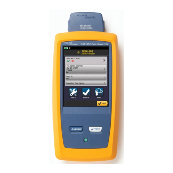
Chapter 1: Get Acquainted Overview of Features The DSX-602 CableAnalyzer main and remote units are rugged, hand-held testers that let you certify, troubleshoot, and document copper network cabling. The DSX-602 includes these features: The testers certify twisted pair cabling to Cat 6A/Class E ... -
Page 10: Contact Fluke Networks
Fluke Networks operates in more than 50 countries worldwide. For more contact information, go to our website. Register Your Product Registering your product with Fluke Networks gives you access to valuable information on product updates, troubleshooting tips, and other support services. If you purchased a Gold Support plan, registration also activates your plan. -
Page 11: Kit Contents
For a list of the contents of your DSX-602 kit, see the list that came in the product’s box or see the lists of models and accessories on the Fluke Networks website. If something is damaged or missing, contact the place of purchase immediately. -
Page 12: W Safety Information
Read all safety information before you use the Product. Carefully read all instructions. Do not open the case. You cannot repair or replace parts in the case. Do not modify the Product. Use only replacement parts that are approved by Fluke Networks. - Page 13 Chapter 1: Get Acquainted WSafety Information Do not touch voltages > 30 V AC rms, 42 V AC peak, or 60 V DC. Do not use the Product around explosive gas, vapor, or in damp or wet environments. ...
- Page 14 Do not put in direct sunlight. Have an approved technician repair the Product. Use only AC adapters approved by Fluke Networks for use with the Product to supply power to the Product and charge the battery.
- Page 15 You can lose a USB flash drive, cause damage to it, or accidentally erase the contents of the drive. Thus, Fluke Networks recommends that you save no more than one day of test results on a flash drive, or that you upload results to LinkWare Live. See Chapter 4.
-
Page 16: Connectors, Keys, And Leds
DSX-602 CableAnalyzer Users Manual Connectors, Keys, and LEDs BK88.EPS Figure 1. Main Tester Connectors, Keys, and LEDs Connector for a link interface adapter LCD display with touchscreen : Starts a test. Turns on the tone generator if a remote tester is not connected to the main tester. - Page 17 Battery” on page 14. RJ45 connector: Lets you connect to a network for access to Fluke Networks cloud services. Micro-AB USB port: This USB port lets you connect the tester to a PC so you can upload test results to the PC and install software updates in the tester.
-
Page 18: Remote Tester Connectors, Keys, And Leds
DSX-602 CableAnalyzer Users Manual BK42.EPS Figure 2. Remote Tester Connectors, Keys, and LEDs Connector for a link interface adapter PASS LED comes on when a test passes. TEST LED comes on during a test. FAIL LED comes on when a test fails. TALK LED comes on when the talk function is on ( ). - Page 19 Chapter 1: Get Acquainted Connectors, Keys, and LEDs TONE LED flashes and the tone generator comes on if you press when a main tester is not connected to the remote. LOW BATTERY LED comes on when the battery is low. The LEDs also have these functions: ...
-
Page 20: About Link Interface Adapters
DSX-602 CableAnalyzer Users Manual About Link Interface Adapters Link interface adapters let you connect the DSX-602 CableAnalyzer to different types of twisted pair links. Figure 3 shows how to attach and remove adapters. Caution To prevent damage to the cables on the permanent link adapters and to make sure your test results are as accurate as possible, do not twist, pull on, pinch, crush, or make kinks in the cables. -
Page 21: How To Prevent Damage To The Permanent Link Adapter Cables
Chapter 1: Get Acquainted About Link Interface Adapters 5 in (13 cm) minimum GPU108.EPS Figure 4. How to Prevent Damage to the Permanent Link Adapter Cables... -
Page 22: Ac Adapter And Battery
DSX-602 CableAnalyzer Users Manual AC Adapter and Battery You can use the AC adapter (model PWR-SPLY-30W) or the lithium ion battery (model VERSIV-BATTERY) to supply power to the tester. To remove the battery, see “Remove the Battery” on page 100. Charge the Battery Before you use the battery for the first time, charge the battery for about 2 hours with the tester turned off. -
Page 23: Check The Battery Status
Chapter 1: Get Acquainted AC Adapter and Battery Check the Battery Status On a main tester The battery status icon is in the upper-left corner of the screen: Battery is full. Battery is approximately half full. If the AC adapter is not connected, the red bar shows that the battery is very low. -
Page 24: Verify Operation
DSX-602 CableAnalyzer Users Manual To see more information about a remote’s battery status Make the connections shown in Figure 6 and turn on both testers. Make sure the connection icon shows at the top of the screen Tap TOOLS, then tap Battery Status. When the AC adapter is not connected, the screen shows the Time Remaining, which is the approximate battery life at the present rate of use. -
Page 25: Connections To See The Status Of A Remote's Battery
Chapter 1: Get Acquainted Verify Operation DSX-602 with two channel adapters and a patch cord DSX-602 with permanent link and channel adapters BK148.EPS Figure 6. Connections to See the Status of a Remote’s Battery... -
Page 26: How To Use The Touchscreen
DSX-602 CableAnalyzer Users Manual How to Use the Touchscreen ™ The DSX-602 main unit’s Taptive user interface lets you use a touchscreen to control the tester. You can operate the touchscreen with your fingertip or with a stylus that is made for projected capacitance touchscreens. -
Page 27: How To Zoom The Screen
Chapter 1: Get Acquainted How to Use the Touchscreen To move the image, drag it in To zoom in, use the reverse- any direction. pinch gesture To quickly go back to 1:1 To zoom out, use the pinch magnification, double-tap the gesture screen. -
Page 28: Change The Language
DSX-602 CableAnalyzer Users Manual Change the Language On the home screen, tap the TOOLS icon, tap Language, then tap a language. Buttons to Do Tests and Save Results When a test is completed and more than one button shows at the bottom of the screen, the tester highlights one in yellow to recommend which one to tap. - Page 29 Chapter 1: Get Acquainted Buttons to Do Tests and Save Results SAVE (yellow), TEST (gray): These buttons show if the test passed and Auto Save is off. When you tap SAVE, you can save the results with an ID that you make or select. When you tap TEST, you can select to save the results or do the test again and not save the results.
-
Page 30: Overview Of Memory Functions
DSX-602 CableAnalyzer Users Manual Overview of Memory Functions You can save approximately 12,700 Cat 6A Autotest results, with plot data included, in the DSX-602 main tester. The capacity available for test results depends on the space used by the software and custom test limits in the tester. To see the memory status On the home screen, tap the TOOLS icon, then tap Memory Status. -
Page 31: About Linkware Applications
PC, organize and examine test results, print professional-quality test reports, and do software updates and other maintenance procedures on your tester. You can download LinkWare PC from the Fluke Networks website. The LinkWare Live Web Application The LinkWare Live web application lets you manage your projects from a desktop or mobile device. -
Page 32: Linkware Stats
DSX-602 CableAnalyzer Users Manual LinkWare Stats The LinkWare Stats Statistical Report software that is included with LinkWare PC software provides statistical analysis of cable test reports and generates browsable, graphical reports. For instructions about LinkWare PC and LinkWare Stats software, see the guides for getting started and the online help available under Help on the LinkWare PC and LinkWare Stats menus. -
Page 33: Chapter 2 Certify Twisted Pair Cabling
Chapter 2: Certify Twisted Pair Cabling Warning Before you use the DSX-602 CableAnalyzer, read the safety information that starts on page 3. The DSX-602 CableAnalyzer Home Screen The home screen (Figure 9) shows important test settings. Before you do a test, make sure these settings are correct. -
Page 34: The Home Screen For The Dsx-602 Cableanalyzer
DSX-602 CableAnalyzer Users Manual LM N BK110.EPS Figure 9. The Home Screen for the DSX-602 CableAnalyzer PROJECT: The project contains the settings for a job and helps you monitor the status of a job. When you save test results, the tester puts them in the project. - Page 35 Chapter 2: Certify Twisted Pair Cabling The DSX-602 CableAnalyzer Home Screen : The number of tests that failed. : The number of tests with an overall marginal result. The test setup panel shows the settings the tester will use when you tap TEST or press .
-
Page 36: Make Sure Your Tester Is Ready To Certify Cabling
To make sure your tester meets its accuracy specifications, follow these guidelines: Keep the tester’s software current. The latest software is available on the Fluke Networks website. See “Update the Software” on page 95. Set the reference for the twisted pair adapters every 30 days. ... -
Page 37: Set The Reference
Make sure the battery is fully charged. Send the testers to a Fluke Networks service center every 12 months for factory calibration. Set the Reference The reference procedure for twisted pair cable sets the baseline for insertion loss, ACR-F, and DC resistance measurements. -
Page 38: Reference Connections For Twisted Pair Cable
DSX-602 CableAnalyzer Users Manual Channel adapters 6 inch (15 cm) reference patch cord Permanent link Channel adapter adapter BK89.EPS Figure 10. Reference Connections for Twisted Pair Cable... -
Page 39: Settings For Twisted Pair Tests
Chapter 2: Certify Twisted Pair Cabling Settings for Twisted Pair Tests Settings for Twisted Pair Tests Table 2 gives descriptions of the settings for twisted pair tests. To set up a project, which includes the settings in Table 2, cable IDs, and operator names, see Chapter 5. - Page 40 DSX-602 CableAnalyzer Users Manual Table 2. Settings for Twisted Pair Tests Setting Description Cable Type Select a cable type that is correct for the type you will test. To see a different group of cable types, tap MORE, then tap a group. To make a custom cable type, tap Custom in the Cable Groups list.
- Page 41 Chapter 2: Certify Twisted Pair Cabling Settings for Twisted Pair Tests Table 2. Settings for Twisted Pair Tests (continued) Setting Description Store Plot Data : The tester does not save plot data for frequency- domain tests or for the HDTDR/HDTDX analyzers. You can see the plots before you save the test and exit the results screen.
- Page 42 DSX-602 CableAnalyzer Users Manual Table 2. Settings for Twisted Pair Tests (continued) Setting Description AC Wire Map The AC Wire Map test lets you do tests on links connected through midspan PoE (Power over Ethernet) devices. See the Technical Reference Handbook. When the AC Wire Map test is on, this icon shows on the home screen: Notes...
-
Page 43: Outlet Configurations
Chapter 2: Certify Twisted Pair Cabling Settings for Twisted Pair Tests T568A T568B Crossover 1000BASE-T Crossover Rollover 2 x Two-Pair Crossed Ethernet Ethernet Two-Pair Two-Pair Crossed Token Ring CSU/DSU USOC Two-Pair USOC Single-Pair ATM/TP-PMD ATM/TP-PMD One Pair (1,2) Straight Crossed M12 Two-Pair M12 Two-Pair Crossed GPU85.EPS... -
Page 44: How To Do An Autotest
DSX-602 CableAnalyzer Users Manual How to Do an Autotest When you tap TEST on the main tester or press on the main or remote tester, the testers do an Autotest. The Autotest includes all the tests necessary to certify that the cabling meets or exceeds the performance requirements specified in the selected test limit. - Page 45 Chapter 2: Certify Twisted Pair Cabling How to Do an Autotest To do an Autotest on twisted pair cable Attach permanent link or channel adapters to the main and remote testers. Make sure that the home screen shows the correct settings for the job.
-
Page 46: Permanent Link Connections
DSX-602 CableAnalyzer Users Manual Horizontal cabling Optional consolidation point Patch panel Wall outlet Start permanent permanent link link Tester with Remote with permanent link permanent link adapter adapter BK97.EPS Figure 13. Permanent Link Connections... -
Page 47: Bad Patch Cord" Message
Chapter 2: Certify Twisted Pair Cabling “Bad Patch Cord” Message Horizontal cabling Hub or switch Optional consolidation point Patch cord Wall from hub outlet or switch Patch Patch cord panels from PC Start channel channel Tester with Remote with channel adapter channel adapter BK96.EPS Figure 14. -
Page 48: Twisted Pair Autotest Results
DSX-602 CableAnalyzer Users Manual Twisted Pair Autotest Results The tests listed below apply to twisted pair cabling. Note Some tests are not included in some test limits. Wire map Resistance Length Propagation delay Delay skew ... -
Page 49: Pass*/Fail* Results
Chapter 2: Certify Twisted Pair Cabling Twisted Pair Autotest Results PASS*/FAIL* Results A result shows an asterisk when measurements are in the tester’s accuracy uncertainty range (Figure 15) and the asterisk is required by the selected test limit. These results are marginal. ... -
Page 50: Wire Map Tab
DSX-602 CableAnalyzer Users Manual WIRE MAP Tab The WIRE MAP tab shows the connections between the ends of the cable under test. The tester compares the connections to the selected Outlet Configuration to get a PASS or FAIL result. If the wire map test fails, you can continue or stop the Autotest. Or, you can tap SCAN ON to do the wire map test continuously while you look for the fault. - Page 51 Chapter 2: Certify Twisted Pair Cabling Twisted Pair Autotest Results The name of the outlet configuration used for the test. The outlet configuration is a setting on the TEST SETUP screen. The wire map of the cabling. The main tester is at the left side of the wire map.
-
Page 52: Performance Tab
DSX-602 CableAnalyzer Users Manual PERFORMANCE Tab The PERFORMANCE tab (Figure 17) shows the overall result for each test that is required by the selected test limit. BA86.EPS Figure 17. PERFORMANCE Tab The test limit and cable type used for the test. To see all the ... -
Page 53: Frequency-Domain Results
Chapter 2: Certify Twisted Pair Cabling Twisted Pair Autotest Results The results are within the limit. The selected test limit does not have a limit for the test, or a dB rule applies. See the Technical Reference Handbook. The results are within the range of accuracy uncertainty for the tester. -
Page 54: Tabular Results Screen For A Frequency-Domain Test
DSX-602 CableAnalyzer Users Manual BA104.EPS Figure 18. Tabular Results Screen for a Frequency-Domain Test The location where the tester made the measurements. To switch between results for the main and remote, tap REMOTE or MAIN ( The results are for the wire pair or pairs shown. To see the results for a different pair or pairs, tap a tab on the right side of the screen ( ... - Page 55 Chapter 2: Certify Twisted Pair Cabling Twisted Pair Autotest Results The measured value. The limit specified by the selected test limit. MARGIN is the difference between the measured value and the limit. The value is in a red box if the measurement exceeds the limit.
-
Page 56: Plot Screen For A Frequency-Domain Test
DSX-602 CableAnalyzer Users Manual BA71.EPS Figure 19. Plot Screen for a Frequency-Domain Test The location of the measurements. To switch between results for the main and remote, tap REMOTE or MAIN ( Measured values for the wire pairs. ... - Page 57 Chapter 2: Certify Twisted Pair Cabling Twisted Pair Autotest Results The vertical scale is the measured value in decibels. The horizontal scale is the frequency range in megahertz. To see help for the screen, tap To switch between results for the main unit and the remote, ...
-
Page 58: Diagnostic Tab
DSX-602 CableAnalyzer Users Manual DIAGNOSTIC Tab If an Autotest on twisted pair cabling fails or has marginal results, the DSX-602 CableAnalyzer automatically gives you HDTDR and HDTDX plots to help you find faults. To see the plots, tap the DIAGNOSTIC tab, then tap the HDTDR or HDTDX panel (Figure 20). -
Page 59: Continuous Tests
Chapter 2: Certify Twisted Pair Cabling Twisted Pair Autotest Results Continuous Tests To do the wire map, length, or resistance test continuously, go to the home screen, tap TOOLS > Single Tests, then tap a test. The wire map test compares the results to the outlet configuration specified by the selected test limit and shows the connections agree or if they do not. - Page 60 DSX-602 CableAnalyzer Users Manual...
-
Page 61: Chapter 3 Certify Coaxial Cabling
Chapter 3: Certify Coaxial Cabling The optional DSX-CHA003 coaxial adapters let you use the DSX-600 CableAnalyzer to certify coaxial cabling for network and video applications. Set the Reference for Coaxial Tests To use DSX-CHA003 adapters, you must set the reference for coaxial tests. -
Page 62: Reference Connections For Tests On Coaxial Cabling
DSX-602 CableAnalyzer Users Manual Notes Set the reference only after the testers are at an ambient temperature between 10 °C and 40 °C (50 °F and 104 °F). The tester will not let you set the reference if the patch cord is longer than 30 cm (12 in). You can also set the reference with a 50 patch cord... -
Page 63: Settings For Coaxial Tests
Chapter 3: Certify Coaxial Cabling Settings for Coaxial Tests Settings for Coaxial Tests Table 3 gives descriptions of the settings for coaxial tests. To set up a project, which includes the settings in Table 3, cable IDs, and operator names, see Chapter 5. To set up a coaxial test On the home screen, tap the test setup panel. - Page 64 DSX-602 CableAnalyzer Users Manual Table 3. Settings for Coaxial Tests Setting Description Cable Type Select a cable type that is correct for the type you will test. To see a different group of cable types, tap MORE, then tap a group. To make a custom cable type, tap Custom in the Cable Groups list.
-
Page 65: How To Do An Autotest
Chapter 3: Certify Coaxial Cabling How to Do an Autotest How to Do an Autotest Figure 22 shows the equipment for tests on coaxial cabling. Notes You can do the HDTDR, length, and resistance tests without a remote tester. See “Tests Without a Remote”... - Page 66 DSX-602 CableAnalyzer Users Manual To do an Autotest Attach coaxial adapters to the main and remote testers. Make sure that the home screen shows the correct settings for the job. To make sure that other settings are correct, tap the test setup panel, make sure the correct test is selected on the CHANGE TEST screen, then tap EDIT to see more settings.
-
Page 67: Examples Of Connections For Tests On Coaxial Cabling
Chapter 3: Certify Coaxial Cabling How to Do an Autotest Data network Disconnect all drop cables DSX-CHA003 DSX-CHA003 COAX ADAPTER COAX ADAPTER IP cameras Surveillance network Router Coaxial segment MoCA MoCA DSX-CHA003 DSX-CHA003 COAX ADAPTER COAX ADAPTER adapter adapter Cable TV Note: Do not do tests through splitters. -
Page 68: Coaxial Autotest Results
DSX-602 CableAnalyzer Users Manual Coaxial Autotest Results Note Not all test limits include all the tests shown in Figure 24. GPU182.EPS Figure 24. Autotest Results for Coaxial Cabling The test limit and cable type used for the test. To see detailed results for a test, tap the panel. ... -
Page 69: About Splitters
Chapter 3: Certify Coaxial Cabling About Splitters The DIAGNOSTIC tab shows the HDTDR analyzer button, which you can tap to see the HDTDR plot. The plot helps you find faults on the cable. The HDTDR plot for coaxial cable includes limit lines and a PASS/FAIL result. -
Page 70: Tests Without A Remote
DSX-602 CableAnalyzer Users Manual Tests Without a Remote You can do the length, resistance, and HDTDR tests without a remote tester. Table 4 describes the effects of a remote on tests. Attach a coaxial adapter to the main tester. Make sure that the home screen shows the correct settings for the job. - Page 71 Chapter 3: Certify Coaxial Cabling Tests Without a Remote Table 4. Remote Requirements for Coaxial Tests Test Remote Requirements* HDTDR Optional. Without a remote, the plot shows large analyzer reflections at the end of the cabling. Resistance A remote or a terminator is required for a loop resistance measurement.
-
Page 72: Connections For Coaxial Tests Without A Remote
DSX-602 CableAnalyzer Users Manual DSX-CHA003 COAX ADAPTER For length measurements, disconnect terminators. See Table 4 on page 63. DSX-CHA003 COAX ADAPTER BK183.EPS Figure 25. Connections for Coaxial Tests Without a Remote... -
Page 73: Continuous Tests
Chapter 3: Certify Coaxial Cabling Continuous Tests Continuous Tests To do the length or resistance test continuously, go to the home screen, tap TOOLS > Single Tests, then tap a test. The length and resistance tests do not compare the results to a test limit. - Page 74 DSX-602 CableAnalyzer Users Manual...
-
Page 75: Chapter 4 Manage Test Results
Chapter 4: Manage Test Results View Saved Results On the home screen, tap the RESULTS icon. The RESULTS screen shows the results in the active project. See Figure 26. To view results saved on a USB flash drive, connect the drive, then tap RESULTS, TRANSFER, USB Flash Drive, Import. -
Page 76: Results Screen
DSX-602 CableAnalyzer Users Manual BA24.EPS Figure 26. RESULTS Screen The name of the active project. : The number of results that passed. This includes individual results for each ID and tests that have an result. : The number of results that failed. This includes individual results for each ID. - Page 77 These icons show when you connect the tester to a network to use Fluke Networks cloud services (see Chapter 6): The tester is connected to a wireless network. The tester is connected to a wired network.
-
Page 78: How To Replace A Saved Result That Failed
DSX-602 CableAnalyzer Users Manual How to Replace a Saved Result that Failed To use the same test settings that were used for the saved result On the home screen, tap the RESULTS icon. On the RESULTS screen, tap a result that failed. Tap TEST AGAIN. - Page 79 Chapter 4: Manage Test Results Delete, Rename, and Move Results To delete results On the MANAGE RESULTS screen, select the results you want to delete. To select all the tests that failed or all the tests that passed, tap Select All Retests or Select All Passes. Tap DELETE, then tap DELETE in the confirmation dialog.
-
Page 80: Manage Results On A Flash Drive
You can lose a USB flash drive, cause damage to it, or accidentally erase the contents of the drive. Thus, Fluke Networks recommends that you save no more than one day of test results on a flash drive. Note The tester reads only USB drives that use the FAT format. -
Page 81: Upload Results To A Pc
Chapter 4: Manage Test Results Upload Results to a PC Import: On the IMPORT RESULTS screen select the project that contains the results you want to import from the flash drive, then tap IMPORT. Delete: On the DELETE RESULTS screen select the project that contains the results you want to delete on the flash drive, then tap DELETE. -
Page 82: View The Memory Status
DSX-602 CableAnalyzer Users Manual adapter Type A USB port Micro-AB USB port BK46.EPS Figure 27. How to Connect the Tester to a PC View the Memory Status To see the memory status On the home screen, tap the TOOLS icon, then tap Memory Status. -
Page 83: Chapter 5 Use Projects
Chapter 5: Use Projects Why Use Projects? ™ The tester’s ProjX management system lets you set up projects that help you monitor the status of a job and make sure that your work agrees with the requirements of the job. You can use a project to do these tasks: Specify the tests that are necessary for a job. -
Page 84: Set Up A Project
DSX-602 CableAnalyzer Users Manual Set Up a Project Refer to the PROJECT screen in Figure 28 on page 77. On the home screen, tap the PROJECT panel, tap CHANGE PROJECT, then tap NEW PROJECT. On the NEW PROJECT screen, enter a name for the project, then tap DONE. -
Page 85: Project Screen
Chapter 5: Use Projects The PROJECT Screen GPU08.EPS Figure 28. PROJECT Screen : The number of DSX CableAnalyzer results that have PASS* results. PASS* results have measurements within the range of accuracy uncertainty for the tester. See “PASS*/FAIL* Results” on page 41. -
Page 86: The Cable Id Setup Screen
DSX-602 CableAnalyzer Users Manual To use a different project, tap CHANGE PROJECT, then tap a project. To make a new project, tap CHANGE PROJECT, then tap NEW PROJECT. TRANSFER lets you export or import projects to or from a flash ... - Page 87 Chapter 5: Use Projects The CABLE ID SETUP Screen BA09.EPS Figure 29. CABLE ID SETUP Screen (after you enter the first and last IDs) First ID and Last ID: The first and last IDs in a set of sequential IDs. ...
-
Page 88: About Next Id Sets
DSX-602 CableAnalyzer Users Manual Total IDs: The number of IDs in the set. This section does not show for ID sets that do not have a Last ID. Tap IMPORT to use an ID set that you downloaded to the tester from LinkWare PC software. -
Page 89: Manage Projects On A Flash Drive
You can lose a USB flash drive, cause damage to it, or accidentally erase the contents of the drive. Thus, Fluke Networks recommends that you save no more than one day of test results on a flash drive. Note The tester reads only USB drives that use the FAT format. -
Page 90: Copy Project Settings To Other Testers
DSX-602 CableAnalyzer Users Manual Import: On the IMPORT PROJECTS screen select the projects you want to import from the flash drive, then tap IMPORT. Delete: On the DELETE PROJECTS screen select the projects you want to delete on the flash drive, then tap DELETE. -
Page 91: Chapter 6 Sync Projects With Linkware ™ Live
If you do not have a LinkWare Live account, click New user? Sign up now!. Enter the information for your account, then click CREATE ACCOUNT. Fluke Networks sends you an email with a LinkWare Live activation code. Open the email, copy the activation code, click the LinkWare Live activation link in the email, paste the activation code into the box in the activation window, then click ACTIVATE. -
Page 92: How To See The Tester's Mac Address
DSX-602 CableAnalyzer Users Manual How to See the Tester’s MAC Address Some networks require users to register their device’s MAC address before they can connect to the network. There are two MAC addresses: one for the wired port and one for the Wi-Fi adapter. -
Page 93: Use Linkware Live Through A Wi-Fi Ethernet Network
Chapter 6: Sync Projects with LinkWare ™ Live Use LinkWare Live Through a Wi-Fi Ethernet Network On the SYNC PROJECTS screen (Figure 30 on page 86), select the projects you want to sync, then tap SYNC. Use LinkWare Live Through a Wi-Fi Ethernet Network The tester can use wireless network channels 1 through 11. -
Page 94: Sync Projects Screen
DSX-602 CableAnalyzer Users Manual If you use other people’s LinkWare Live accounts, the ORGANIZATION screen shows. Tap the organization you want to use. On the SYNC PROJECTS screen (Figure 30), select the projects you want to sync, then tap SYNC. See Figure 30: Projects in the On this tester section are possibly also in ... - Page 95 Chapter 6: Sync Projects with LinkWare ™ Live Use LinkWare Live Through a Wi-Fi Ethernet Network By default, the active project is selected to sync. Projects in the Available only on LinkWare Live section have project settings you can download to the tester. If you download these projects, only test settings and cable IDs are downloaded.
-
Page 96: Change The Network Settings
DSX-602 CableAnalyzer Users Manual Change the Network Settings It is not usually necessary to change the wired or Wi-Fi network settings before you try to make a connection. But for example if you must use static addressing, you can get to the settings on the NETWORK screen. - Page 97 Chapter 6: Sync Projects with LinkWare ™ Live Change the Network Settings Table 5. Settings for the Wi-Fi Connection Setting Description Address Most networks use DHCP. DHCP address SSID: The tester does a scan for wireless networks and settings shows a list of available networks. Select the correct SSID. To connect to a hidden network, tap ADD SSID.
-
Page 98: Delete Wi-Fi Settings And Passwords
DSX-602 CableAnalyzer Users Manual Table 5. Settings for the Wi-Fi Connection (continued) Setting Description Static address Enter an IP address for the tester and the Subnet Mask, settings Gateway address, and DNS1 and DNS2 addresses for the network. If you are not sure what to enter, speak to the network administrator. -
Page 99: Sign Your Tester Out Of Linkware Live
Chapter 6: Sync Projects with LinkWare ™ Live Sign Your Tester Out of LinkWare Live Sign Your Tester Out of LinkWare Live On the home screen, tap the TOOLS icon, then tap Sign In. On the LWL SIGN IN screen, tap SIGN OUT. Or, turn off the tester. - Page 100 DSX-602 CableAnalyzer Users Manual...
-
Page 101: Chapter 7 Maintenance
If you replace parts that are not specified as replacement parts, the warranty will not apply to the product and you can make the product dangerous to use. Use only service centers that are approved by Fluke Networks. Caution... -
Page 102: Verify Operation
DSX-602 CableAnalyzer Users Manual Verify Operation The tester does a self test when you turn it on. If the tester shows an error or does not turn on, refer to “If the Tester Does Not Operate as Usual” on page 102. Clean the Tester To clean the touchscreen, turn off the tester, then use a soft, lint- free cloth that is moist with water or water and a mild detergent. -
Page 103: See Information About The Tester
New software gives you access to new features and the latest test limits and cable types. Software updates are available on the Fluke Networks website. You can use a PC to install a software update, or connect an updated main unit to a remote or to another main unit to update those units. -
Page 104: Use A Pc To Update The Software
Micro-AB USB port on the tester to a type A USB port on the PC. See Figure 31. LinkWare PC automatically tells you if new software for the tester is available on the Fluke Networks website, and lets you install the software. Note Older versions of LinkWare PC do not start the update procedure automatically. -
Page 105: Use An Updated Main Tester To Update Other Testers
Chapter 7: Maintenance Update the Software adapter Type A USB port Micro-AB USB port BK46.EPS Figure 31. How to Connect the Tester to a PC Use an Updated Main Tester to Update Other Testers Turn on both testers and connect the AC adapters to both testers. -
Page 106: How To Connect Units Together To Update The Software
DSX-602 CableAnalyzer Users Manual adapters Remote Updated main unit Type A Micro-AB USB port USB port adapters Main unit Updated main unit Type A Micro-AB USB port USB port BK116.EPS Figure 32. How to Connect Units Together to Update the Software... -
Page 107: Use Linkware Live To Update The Software
Chapter 7: Maintenance Update the Software Use LinkWare Live to Update the Software Use an appropriate cable to connect the tester’s RJ45 Ethernet port to a network port, or connect a Wi-Fi adapter to the tester’s type A USB port. On the home screen, tap the SYNC icon. -
Page 108: Extend The Life Of The Battery
DSX-602 CableAnalyzer Users Manual Extend the Life of the Battery Warning To prevent possible fire, electric shock, or personal injury, read the warnings about the rechargeable battery under “WarningX” on page 4. Do not frequently let the battery discharge completely. Do not keep the battery at temperatures below -20 C (-4 ... -
Page 109: Traceable Calibration Period
To see when the tester last received a factory calibration, tap the TOOLS icon on the home screen, then tap Version Information. Options and Accessories For a complete list of options and accessories go to the Fluke Networks website at www.flukenetworks.com. To order options and accessories, contact an authorized Fluke... -
Page 110: If The Tester Does Not Operate As Usual
If the condition continues, contact Fluke Networks for assistance, or search the Fluke Networks Knowledge Base for a solution. If you contact Fluke Networks, have available the serial number, software and hardware versions, and calibration date for the tester, if possible.
Need help?
Do you have a question about the CableAnalyzer DSX-602 and is the answer not in the manual?
Questions and answers