Table of Contents
Advertisement
Quick Links
Introduction
This Service Information Sheet provides the
following service information for the DSP Fiber
Optic Meter (hereafter referred to as the FOM) with
serial numbers < 79370000.
•
Parts and warranty service information
•
•
•
Cleaning procedures
•
•
•
Procedures for disassembling and
reassembling the FOM
•
•
Parts And Accessories lists
•
Schematic
•
Diagram showing calibration measurement
and adjustment points
For operating instructions, refer to the
DSP-FOM/DSP-FTK Fiber Optic Accessory
Instruction Sheet.
PN 616141
September 1996, Rev. 2, 1/02
©1996-2002 Fluke Networks, Inc. All rights reserved. Printed in USA. Product names are trademarks of their respective companies.
Fluke DSP-FOM Specs
Provided by www.AAATesters.com
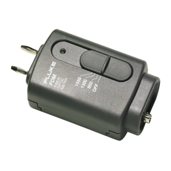
Service Information Sheet for Serial Numbers < 79370000
Fiber Optic Meter
Parts and Warranty Service
The FOM is warranted to be free from defects in
material and workmanship for one year, while
under normal use. Parts and repairs are warranted
for 90 days.
Refer to the Instruction Sheet for the complete
warranty statement.
To order parts, or for warranty service, contact
Fluke as follows:
U.S.A.: 1-888-993-5853
Canada: 1-800-363-5853
Europe: +31-402-675-200
Japan: +81-3-3434-0181
Singapore: +65-738-5655
Anywhere in the world: +1-425-446-4519
For operating assistance in the USA, call
1-800-283-5853.
Visit the Fluke Networks web site at
www.flukenetworks.com.
DSP-FOM
Advertisement
Table of Contents

Subscribe to Our Youtube Channel
Related Manuals for Fluke DSP-FOM


Summary of Contents for Fluke DSP-FOM
- Page 1 Visit the Fluke Networks web site at For operating instructions, refer to the www.flukenetworks.com. DSP-FOM/DSP-FTK Fiber Optic Accessory Instruction Sheet. PN 616141 September 1996, Rev. 2, 1/02 ©1996-2002 Fluke Networks, Inc. All rights reserved. Printed in USA. Product names are trademarks of their respective companies.
- Page 2 DSP-FOM Fiber Optic Meter light to be measured into the FOM. The RJ45 Specifications connector outputs a calibrated voltage via a cable to Accuracy is specified for a period of one year after the host CableMeter test tool. Other signals present calibration, at 18 °C to 28 °C (64 °F to 82 °F) with...
- Page 3 (and Page Up/Page Cleaning the Optical Connector Down softkeys if necessary) to select the Most problems with optical power meters result applicable standard for the DSP-FOM; then from contaminated connectors. Therefore, always press . Use the arrow keys to select Multimode as the cable type;...
- Page 4 FOM. Step 1: Preparing for Calibration To prepare for calibration, proceed as follows: Disassembling and Reassembling 1-1. Remove the dust cap from the DSP-FOM. the FOM 1-2. Connect a voltage supply of 8 V dc WCaution ±1.0 V dc to the FOM battery strap.
- Page 5 Service Information Sheet for Serial Numbers < 79370000 Calibration Adjustments 3-3. Use P in from step 3-1, V ref from step Step 2: Coarse Calibration Adjustment 2-5, and the transfer function below to Refer to the schematic in Figure 1 and the drawing calculate Vo: in Figure 2 for the locations of measurements and 9R = ...
- Page 6 (Table 3) are available from Fluke. position. 5-2. Set the 1550 nm light source to -10 dBm Table 2. Fluke Replacement Parts for the DSP-FOM ±0.05 dBm. Use the reference power meter to measure the source output power level. Fluke Part Record this level as P in for use in step 5-4.
- Page 7 Service Information Sheet for Serial Numbers < 79370000 Fiber Optic Meter Schematic for SN < 79370000 Dt11f.eps Figure 1. Fiber Optic Meter Schematic for SN < 79370000...
- Page 8 DSP-FOM Fiber Optic Meter Pin 7 Pin 1 Pin 5 Pin 7 FPM2-00-0001 Dt14f.eps Figure 2. Calibration Measurement and Adjustment Points for SN < 79370000...
Need help?
Do you have a question about the DSP-FOM and is the answer not in the manual?
Questions and answers