Table of Contents
Advertisement
Advertisement
Table of Contents

Related Manuals for Fluke DSX-600 CableAnalyzer


Summary of Contents for Fluke DSX-600 CableAnalyzer
- Page 1 Copper Cabling Troubleshooting Handbook...
-
Page 3: Table Of Contents
Contents Introduction . . . . . . . . . . . . . . . . . . . . . . . . . . . . . . . . . . 4 Why the need for advanced diagnostics? Troubleshooting Basics . -
Page 4: Introduction
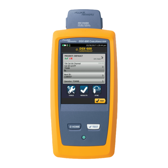
This handbook guides you through the troubleshooting of advanced structured cabling systems using the Fluke Networks DSX-600 CableAnalyzer™ so you can increase your productivity and deliver better value to your organization. -
Page 5: Troubleshooting Basics
• Is the tester within its operating temperature range and in calibration? Remember that your Fluke Networks DSX-600 CableAnalyzer™ is a very accurate instrument that measures small noise disturbances in cables. These instruments are calibrated in the factory before shipping and this calibration should be verified every 12 months in an authorized Service Center. -
Page 6: Link Models
Link models To obtain meaningful results, it is essential to select the appropriate autotest and link model. Permanent Link The Permanent Link performance is defined in such a way that after adding good patch cords to a passing link, the channel performance is automatically met. By good patch cords, we mean patch cords that pass the same class or category rating as the link or a higher level of performance. - Page 7 The Permanent Link shown in Figure 1 includes an optional Consolidation Point. Other Permanent Link models may have a second patch panel instead of the TO which is typically seen in a Data Center. The Permanent Link measurement includes the RJ45 plug at the end of the test lead, but does not include the cable portion of the test lead or connection to the test equipment (See Figure 1).
-
Page 8: Channel
Channel Channel measurements are typically performed when restoring a service or to verify the existing cabling for application support. The maximum length allowed for a Channel is 100 meters. It is uncommon to perform Channel tests at the conclusion of a new installation, since the patch cords that belong to each link are rarely available at that time. -
Page 9: The Automated Dsx-600 Diagnostics
The automated DSX-600 diagnostics When an Autotest fails or delivers a “marginal” pass result, the DSX-600 can use its diagnostic capabilities to find the cause of the marginal failures. First, let us review what a marginal test is. The margin of a test is the difference between the measured value and the applicable Pass/Fail limit value. - Page 10 If the cabling link fails to pass the wire map test - the test which verifies that all 8 wires connect the right pins at either end of the cable - the tester halts and presents a window saying ‘Warning Bad Wire Map”. If you press OK, then the wire map diagram is shown with the option to turn ‘SCAN ON’...
-
Page 11: Shield Integrity Test
Shield Integrity Test Wire Map testers use DC Resistance measurements to ensure the shield is correctly terminated and presented in a cabling system. In Data Centers, where the shield is typically grounded at both ends, any wire map tester will report the shield as connected, even if one of the ends is not. - Page 12 To find out more about these diagnostic capabilities let’s have a look at the HDTDR and HDTDX capabilities of the DSX-600. Figure 6 The DSX-600 CableAnalyzer can make Shield integrity measurements using TDR techniques that can prevent false shield test passes.
-
Page 13: Hdtdr Diagnostics
The two parameters that provide the time domain information are HDTDX (High Definition Time Domain Crosstalk) and HDTDR (High Definition Time Domain Reflectometry). As the name indicates, the HDTDX parameter shows the profile of crosstalk happening along the link-under-test while HDTDR shows signal reflections along the link. - Page 14 Now let’s run the HDTDR diagnostics, the results of which are shown in figure 8. First let’s find and view the worst pair which was pair 7,8. Now let’s pinch and zoom on the vertical axis to see the 1% horizontal grid lines in greater detail. Events should not exceed 0.8% so we have drawn red lines on the diagram to make it easier to see which and how many events pass the 0.8% lines.
-
Page 15: Hdtdx Diagnostics
So let’s make a HDTDR diagnostic measurement on this link to see if it can tell us where the water is. We can see the results in figure 10. The results show most of the Return Loss is happening within the first six meters of the cable. The first event where the water begins is normally in the region of 6% to 15%. - Page 16 Figure 12 HDTDX showing connectors at the start and middle of the link. On analyzing the HDTDX trace we see two pulses, one at the beginning 0.0 meters, one in the middle at 6.0 meters and the end of the cable is at 11 meters, this showing us the connectors in the link.
- Page 17 This time we have a NEXT of 28.9 dB with a margin of -6.0 dB at 267.0 MHz. So to find out where this is happening along the cable, we need to run the HDTDX diagnostic test. We see the results for this on figure 14. Again we view the worst pair 3,6-4,5 and we see the far end connector far exceeds the ideal of 30%, it’s nearly 60%.
-
Page 18: Causes Of Cabling Faults
Causes of cabling faults For each of the required TIA and ISO structured cabling measurements, you will find troubleshooting tips to help quickly pinpoint the cause of failures when they occur. In some instances, you will find suggested reasons why the measurement does not fail in cases you would expect to see a failure. -
Page 19: Length
Length Test Result Possible Cause of Result Length exceeds limits • Cable is too long – check for coiled service loops and remove in this case • NVP (nominal Velocity of Propogation) is set incorrectly Length reported is • Intermediate break in the cable shorter than known •... -
Page 20: Next And Psnext
NEXT and PSNEXT Test Result Possible Cause of Result FAIL or PASS* • Poor twisting at connection points • Poorly matched plug and jack (Category 6/Class E applications) • Incorrect link adapter (Cat 5 adapter for Cat 6 links) • Poor quality patch cords •... -
Page 21: Return Loss
Return Loss Test Result Possible Cause of Result FAIL or PASS* • Patch cord impedance not 100 ohms • Patch cord mishandling causes changes in impedance • Installation practices (untwists or kinks of cable - the original twists should be maintained as much as possible for each wire pair) •... -
Page 22: Acr-F And Ps Acr-F (Older Names: Elfext And Pselfext)
ACR-F and PS ACR-F (older names: ELFEXT and PSELFEXT) Test Result Possible Cause of Result FAIL or PASS* • General rule: troubleshoot NEXT problems first. This normally corrects any ACR-F (ELFEXT) problems • Service loops with many tightly coiled windings Resistance Test Result Possible Cause of Result... -
Page 23: Architects, Consultants And Designers Pages
Architects, Consultants and Designers pages Consult the Fluke Networks web page for product information as well as updates in standards or white papers on best practices. Go to www.flukenetworks.com/design... -
Page 24: Conclusion
The Fluke Networks certification test tools have always provided unique and powerful diagnostics assistance to installation technicians. By knowing the nature of typical faults, and how the tester’s diagnostics report them, you can significantly reduce the... -
Page 26: Cableanalyzer Comparison Guide
The DSX-600 provides essential Cat 6A and Class E Copper Certification featuring ten second test times and advanced user interface. Manage jobs and testers from any smart device over Wi-Fi with LinkWare™ Live. Features legendary Fluke Networks reliability backed by worldwide support. Feature DSX-600 CableAnalyzer ™... - Page 27 DSX-5000 CableAnalyzer ™ DSX-8000 CableAnalyzer ™ Cat 6A and Class F Fastest, most accurate Cat 8 and Class I/II copper tester copper cable tester 1000 MHz 2000 MHz 16 sec Cat 8 / Class I/II 10 sec Class E /Cat 6 8 sec Class E...
- Page 28 For additional resources to help you establishCopper Testing Best Practices Visit www.flukenetworks.com/CBPPG P.O. Box 777, Everett, WA USA 98206-0777 Fluke Networks operates in more than 50 countries worldwide. To find your local office contact details, go to www.flukenetworks.com/contact. ©2017 Fluke Corporation. All rights reserved.
Need help?
Do you have a question about the DSX-600 CableAnalyzer and is the answer not in the manual?
Questions and answers