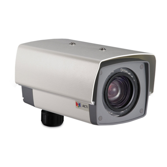
Summary of Contents for ACTi KCM-5511
- Page 1 Outdoor-Ready Box Mounting on a Straight Wall using the Bracket Installation Guide For Models: KCM-5511 / KCM-5611 / KCM-5x11E 2013/12/06...
-
Page 2: Table Of Contents
Step 5: Install the Camera ................. 8 Step 7: Access the Camera Live View ........... 10 Appendices ............... 11 Connecting a Power Adaptor (Optional) ..........11 Connecting DI/DO Devices (Optional) ............ 13 Connecting a Serial Device (Optional) ........... 16 Safety Information ............18 www.acti.com... -
Page 3: Installation Procedures
Step 1: Install the Bracket 1. Remove the screw to detach the camera holder from the bracket. Set the holder aside for later use. 2. Attach the bracket to the pole mount using the three (3) screws supplied in the pole mount kit. www.acti.com... -
Page 4: Step 2: Remove The Back Cover
1. From the network side, insert the Ethernet cable and other cables (if any) through the flex conduit. NOTE: To connect an external power adaptor, digital input/output (DI/DO) or serial devices, insert the cables without connectors through the flex conduit and as well as audio input/output device cables at this point. www.acti.com... - Page 5 2. Insert the clamping nut through the flex conduit. 3. Insert the sealing insert and attach it at the end of the flex conduit. 4. Detach the conduit gland from the back cover of the camera as shown below: Sealing Insert Clamping Nut Conduit Gland Body www.acti.com...
- Page 6 Ethernet and Power Adaptor Cable 6. Insert the sealing insert into the conduit gland body. 7. Attach the clamping nut to complete the cable solution. NOTE: Make sure the clamping nut is tightly attached to the conduit gland body to avoid water leak. www.acti.com...
-
Page 7: Step 4: Connect The Ethernet Cable
11 for more information). Sample image below. Memory Card Slot Audio In /Out Jacks 12V Power Connector Serial Connector Digital Input / Output (DI/DO) Connector 2. When done, close the back cover by tightening the three (3) screws. www.acti.com... -
Page 8: Step 5: Install The Camera
2. Attach the two (2) screws (supplied in the bracket package) to secure the camera to the holder. 3. Align the screw hole of the holder to the bracket as you insert the excess length of flex conduit back into the pole mount. www.acti.com... - Page 9 6. As needed, loosen the two (2) side screws of the holder and then move the camera up or down to adjust the camera viewing angle. Then, tighten the two (2) side screws to fix the position. www.acti.com...
-
Page 10: Step 7: Access The Camera Live View
Step 6: Access the Camera Live View Connect the other end of the Ethernet cable to a PoE switch and access the camera live view. For more information on how to access the camera Live View, download the camera Hardware Manual from the website (http://www.acti.com) www.acti.com... -
Page 11: Appendices
1. Loosen the screws of the 12V and GND pins of the power terminal block. 2. Take note that a standard power adaptor cable has two (2) different wires: Connects to GND Pin White stripe: Connects to 12V Pin www.acti.com... - Page 12 4. Tighten the screws of the 12V pin and the GND pins to secure the wire connection. 5. Set the prepared power adaptor for connection later. Below is an example of a power adaptor with an attached terminal block. NOTE: The power adaptor is not bundled in the package. www.acti.com...
-
Page 13: Connecting Di/Do Devices (Optional)
Mapping Instructions Connect the wires of one output device to DO2 (Pin 1) Digital Output 2 and 12V (Pin 3). (DO2) Connect the wires of another output device to DO1 Digital Output 1 (Pin 5) and 12V (Pin 5). (DO1) www.acti.com... - Page 14 In this case, wire connection to Pins 1 to 4. Use the GND and DI2 pins to connect a DI device and use the 12V and DO2 pins to connect a DO device. See wiring scheme below: Consequently, to connect a second DI or DO device, wire the connection to Pins 5 to 8. www.acti.com...
- Page 15 The illustration below is a graphic example of connecting a relay to a high voltage DO device. 110V-220V AC External Power Source Relay (DO1 Device) Camera Illuminator NOTE: For more information on DI/DO connections, please refer to the Knowledge Base article All about Digital Input and Digital Output downloadable from the link below (http://www.acti.com/kb/detail.asp?KB_ID=KB20091230001). www.acti.com...
-
Page 16: Connecting A Serial Device (Optional)
For example, some devices may have TX – pin labeled as "A” or “485 -”, etc. Refer to the scanner documentation or contact the manufacturer to verify the corresponding pin labels and ensure proper wiring connection. www.acti.com... - Page 17 CAUTION: Incorrect wiring may cause damage to the connected devices. DISCLAIMER: ACTi will not be responsible for any damage caused by improper wiring. 2. Connect a ground wire to one of the GND terminal pins of your camera (via Power or DI/O terminals) to complete the connection.
-
Page 18: Safety Information
Do not use attachments not recommended by the video product manufacturer as they may cause hazards. Do not use accessories not recommended by the manufacturer Only install this device in a dry place protected from weather Servicing Do not attempt to service this video product yourself. Refer all servicing to qualified service personnel. www.acti.com... - Page 19 Safety Check Upon completion of any service or repairs to this video product, ask the service technician to perform safety checks to determine if the video product is in proper operating condition. www.acti.com...


Need help?
Do you have a question about the KCM-5511 and is the answer not in the manual?
Questions and answers