
Related Manuals for Emerson EIM TEC2 500


Summary of Contents for Emerson EIM TEC2 500
- Page 1 Quick-Start Guide E2K-210-05-18 Rev. 3 September 2018 EIM TEC2 Electric Actuator with Model 500 Quick-Start Guide (Model 500 Discontinued)
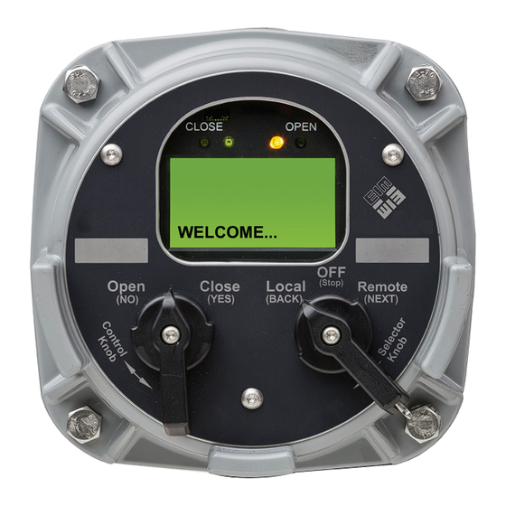
- Page 3 Quick-Start Guide Welcome to TEC2 E2K-210-05-18 Rev. 3 September 2018 Welcome to TEC2 The TEC2 actuator’s Local Display Module (LDM) and Remote Display Module (RDM) provide easy-to-read actuator information. The screen graphics will display the mode of operation, valve status, position, torque, and alarm symbols. The message center will display actuator setup options, data entry feedback, and alarm messages.
-
Page 4: Factory Settings
If full data was not provided when ordering or if changes are needed, see the TEC2 Installation & Operation Manual (E2K-420-0117), which can be found at www.emerson/eim. Power Actuator Verify the voltage rating on the unit nameplate. - Page 5 Quick-Start Guide Setting Valve Position Limits Initially E2K-210-05-18 Rev. 3 September 2018 Setting Valve Position Limits Initially STOP YES, LOCAL YES, Release quickly. Place the selector knob in the STOP position. Then toggle the control knob in rapid succession to YES, then NO, then YES, then NO and release.
-
Page 6: Operation
Quick-Start Guide Setting Position Limits for Electrical Operation E2K-210-05-18 Rev. 3 September 2018 Setting Position Limits for Electrical Operation STEP 1: CLOSED Valve Position STOP LOCAL CLOSE Hold until desired position is reached. Turn the selector knob to the “LOCAL” position. Hold the control knob in the “CLOSE” position until desired position is reached. - Page 7 Quick-Start Guide Setting Position Limits for Electrical Operation E2K-210-05-18 Rev. 3 September 2018 Setting Position Limits for Electrical Operation STEP 2: OPEN Valve Position STOP OPEN LOCAL Hold until desired position is reached. Turn the selector knob to the “LOCAL” position. Hold the control knob in the “OPEN” position until desired position is reached.
- Page 8 Quick-Start Guide Setting Position Limits for Manual Operation E2K-210-05-18 Rev. 3 September 2018 Setting Position Limits for Manual Operation STEP 1: CLOSED Valve Position Depress Release STOP LOCAL declutch, declutch, rotate handwheel until... declutch is fully engaged. Turn the selector knob to the LOCAL position. At the “CLOSE VALVE THEN SELECT STOP” prompt, depress the declutch lever while rotating the handwheel until the clutch is fully engaged.
- Page 9 Quick-Start Guide Setting Position Limits for Manual Operation E2K-210-05-18 Rev. 3 September 2018 Setting Position Limits for Manual Operation STEP 2: OPEN Valve Position Depress Release STOP LOCAL declutch, declutch, rotate handwheel until... declutch is fully engaged. Turn the selector knob to the LOCAL position. At the “OPEN VALVE THEN SELECT STOP” prompt, depress the declutch lever while rotating the handwheel until the clutch is fully engaged.
- Page 10 Quick-Start Guide Check the Open/Closed Settings E2K-210-05-18 Rev. 3 September 2018 Check the Open/Closed Settings Valve Closed Valve Open As you operate the valve in the close direction, verify As you operate the valve in the open direction, verify that the green LED is blinking. When fully closed is that the red LED is blinking.
-
Page 11: Valve Settings
Quick-Start Guide Changing the Valve Settings E2K-210-05-18 Rev. 3 September 2018 Changing the Valve Settings STOP YES, YES, Release quickly. Turn the selector knob to the STOP position then toggle the control knob in rapid succession to YES, then NO, then YES, then NO and release. - Page 12 Network Controlled Quick-Start Guide E2K-210-05-18 Rev. 3 September 2018 Changing the Valve Settings Until appears. Answer NO to the Setup prompts until “CHANGE SETTINGS?” appears. Answer YES. “ACCEPT PASSCODE CHARACTER 1?X” appears. The factory default passcode is 000. Do not change the password without recording the new password.
-
Page 13: Enter Passcode
Quick-Start Guide Network Controlled E2K-210-05-18 Rev. 3 September 2018 Changing the Valve Settings Enter Passcode ...to advance If passcode to correct character is character. correct... Use the control knob and answer YES if the passcode character is correct. If not, use NO to advance incrementally to the correct character. -
Page 14: Setting Limits
Quick-Start Guide Changing the Valve Settings E2K-210-05-18 Rev. 3 September 2018 Changing the Valve Settings Setting Limits Advance to the “SET VALVE TRAVEL LIMITS” prompt and answer YES. Proceed to set limits. Changing the Valve Settings... - Page 15 Answer YES. Hold the control knob in the NO position until the correct address appears. Answer YES. Unit is now network controlled. If other configuration changes are needed, please see the TEC2 Installation & Operation Manual (E2K-420-0117), which can be found at www.emerson/eim. Network Controlled...
- Page 16 Quick-Start Guide Saving the Changes E2K-210-05-18 Rev. 3 September 2018 Saving the Changes CHANGES? Advance to the “SAVE CHANGES?” prompt and answer YES to save the changes. Saving the Changes...
- Page 18 Tianjin 301700 Holland Fasor 6 P. R. China Székesfehérvár 8000 The Emerson logo is a trademark and service mark of Emerson Electric Co. T +86 22 8212 3300 Hungary is a mark of one of the Emerson family of companies.
Need help?
Do you have a question about the EIM TEC2 500 and is the answer not in the manual?
Questions and answers