Advertisement
Available languages
Available languages
Quick Links
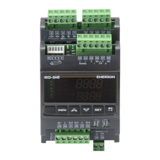
EXD-SH1/2 Controller with ModBus communication
G e n e r a l i n f o r m a t i o n :
EXD-SH1/2 are stand-alone superheat and or temperature controllers. EXD-SH1 is
intended for operation of one bipolar electrical control valve whereas EXD-SH2 is
designed for operation of two independent bipolar electrical control valves.
A table of the available application possibilities is listed below:
Controller
Circuit 1: Main function
EXD-SH1
Superheat or temperature control
EXD-SH2
Superheat or temperature control
Notes:
It is possible to use only circuit 1 from EXD-SH2. In this case, the circuit 2 must
be disabled (C2 parameter) and the sensors and the valve for the second circuit
are not needed.
ModBus communication is described in a Technical Bulletin and it is not
covered by this document.
T e c h n i c a l d a t a :
Power supply
24VAC/DC +10%/-10% 50/60HZ,
Power consumption
EXD-SH1: 25VA
Plug-in connector
Removable screw terminals wire size 0.14...1.5 mm
Protection class
IP00
ECN-N... / TP1... (temperature range down to -45°C)
Temperature sensors
ECN-Z... (temperature range down to -80°C ultra low
temperature)
Allowable
operating/surrounding
0...+55°C
temperature
Maximum cable distance
50 cm
between EXD-SH and
AWG 18 wire size (≥ 1mm
EXD-PM
Pressure sensors
PT5N, PT5N-FLR or ratiometric probes
Output alarm relay current
Resistive Load 24 V AC/DC, 1 A
rating
Inductive Load 24 V AC/DC, 0.5 A
Contact is closed:
During alarm condition
Contact is open:
During normal operation and supply power OFF
Valves:
Stepper motor output
Mounting
For standard DIN rail
Marking
Warning:
EXD-SH1/2 (EXD-PM, ECP-024) has a potential ignition source and does not
comply with ATEX requirements. Installation only in non-explosive
environment. For flammable refrigerants only use valves and accessories
approved for it!
D i m e n s i o n s ( m m ) :
S a f e t y i n s t r u c t i o n s :
• Read operating instructions thoroughly. Failure to comply can result in device
failure, system damage or personal injury.
• It is intended for use by persons having the appropriate knowledge and skill.
• Before installation or service disconnect all voltages from system and device.
• Do not operate system before all cable connections are completed.
• Do not apply voltage to the controller before completion of wiring.
• Entire electrical connections have to comply with local regulations.
• Inputs are not isolated, potential free contacts needed to be used.
.
Emerson Climate Technologies GmbH
Am Borsigturm 31 I 13507 Berlin I Germany
Operating instructions
capability for electrical control valves
Circuit 2: Main function
Superheat Control
EXD-SH2: 50VA
2
)
EX4-8 (EX4-7-FLR)
CV4-7
,
www.climate.emerson.com/en-gb
• Disposal: Electrical and electronic waste must NOT be disposed of with other
commercial waste. Instead, it is the user responsibility to pass it to a
designated collection point for the safe recycling of Waste Electrical and
Electronic Equipment
information, contact your local environmental recycling center.
T e m p e r a t u r e s e t t i n g i n n o r m a l s e n s e
(Controller function as temperature controller)
Valve opening
100%
2
0%
1tAL
T e m p e r a t u r e s e t t i n g i n r e v e r s e s e n s e
(Controller function as temperature controller)
Valve opening
100%
0%
1tAL
E l e c t r i c a l c o n n e c t i o n a n d w i r i n g :
• Refer to the electrical wiring diagram for electrical connections.
• Note: Keep controller and sensor wiring well separated from supply power
cables. Minimum recommended distance 30 mm.
• When connecting the wires of the EXV-M... (electrical plug of valves)
consider the color coding as follows:
EXV-M...: WH: White;
• The digital input DI1 (EXD-SH1/SH2) and DI2 (EXD-SH2) are the interfaces
between EXD-SH1/2 and upper level system controller if the Modbus
communication has not been used. The external digital inputs must be free of
potential (dry contact) and shall be operated in function system's
compressor/demand.
Operating condition
Compressor starts/run
Compressor stops
Note: Connecting any EXD-SH1/2 inputs to the supply voltage will permanently
damage the EXD-SH1/2
EXD-SH12_OI_EN_DE_FR_IT_PL_RU_0720_R04_865917.docx
(WEEE
directive 2012/19/EU). For further
%
1tbd
1tst
%
1tbd
1tst/
BK: Black; BN: Brown; BL: Blue
Digital input status
External contact to be closed (Start)
External contact to be open (Stop)
Temperature
1tAH
Temperature
1tAH
Date: 29.07.2020
Advertisement

Related Manuals for Emerson EXD-SH1


Summary of Contents for Emerson EXD-SH1
- Page 1 EXV-M…: WH: White; BK: Black; BN: Brown; BL: Blue • The digital input DI1 (EXD-SH1/SH2) and DI2 (EXD-SH2) are the interfaces S a f e t y i n s t r u c t i o n s : between EXD-SH1/2 and upper level system controller if the Modbus communication has not been used.
- Page 2 Operating instructions EXD-SH1/2 Controller with ModBus communication capability for electrical control valves Wiring options: UPS (ECP-024) /Supercap (EXD-PM) UPS for up to two controllers 24 V One supercap for one EXD-SH1 VAC/ See parameter 2uP 24 V 24 V Two supercaps...
- Page 3 • Press both the buttons for more than 5 seconds. • Apply supply voltage 24V to EXD-SH1/2 while the digital input (DI1/DI2) is open. • A flashing “0” is displayed in upper and “PAS” at lower. The valve will be driven to close position.
- Page 4 1 = ECN-Z60 ( -80°C…-40°C) for R23 Superheat control circuit1 (Td factor) Warning -Flammable refrigerants: Display 1/10K EXD-SH1/2 (EXD-PM, ECP-024) has a potential ignition source and does not High superheat alarm mode comply with ATEX requirements. Installation only in non-explosive 0 = disabled 1 = enabled auto-reset;...
- Page 5 50% and 100% higher. This false valves are used, then the ACF alarm will be displayed. signal leads to improper operation of EXD-SH1/2 controller and can lead to • Ratiometric pressure transmitters cannot be selected in conjunction with R744.
- Page 6 BK: Schwarz; BN: Braun; BL: Blau • Die Digitaleingänge DI1 (EXD-SH1/SH2) und DI2 (EXD-SH2) sind die S i c h e r h e i t s h i n w e i s e : Schnittstellen zwischen EXD-SH1/2 und dem übergeordnetem Systemregler, •...
- Page 7 Klasse II zu verwenden. Die 24V Leitungen dürfen nicht geerdet werden. Wir empfehlen die Verwendung jeweils separater EMERSON Transformatoren für EXD-SH1/2 Regler und die Regler anderer Hersteller, weil unter Umständen über die Erdleitungen Kurzschlüsse entstehen können. • Wenn EXD-PM angeschlossen ist, ist es notwendig, dass der EXD-SH-Regler und die EXD-PM-Kondensatoren eigene Transformatoren haben.
- Page 8 • Sobald die wichtigsten Parameter eingestellt und gespeichert sind, ist der Regler • Diese Abfolge kann für alle einzustellenden Parameter wiederholt werden. EXD-SH1/2 fertig für die Inbetriebnahme. Alle anderen Parameter könne auch während des Betriebes oder im Stand-By Modus verändert werden.
- Page 9 (Kp Faktor) Display 1/10K Überhitzungsregelung Kreislauf 1 (Ti Faktor) Warnung – Brennbare Kältemittel Überhitzungsregelung Kreislauf 1 EXD-SH1/2 (EXD-PM, ECP-024) hat eine potentielle Zündquelle und (Td Faktor) Display 1/10K entspricht nicht den ATEX Bestimmungen. Installation nur in nicht Alarm „zu große Überhitzung“...
- Page 10 • Ratiometrische Drucktransmitter können nicht mit R744 gewählt werden. Signal geliefert bekommen (50%-100% höher als der entsprechende Druck- wert). Diese Störung kann zur Fehlfunktion des EXD-SH1/2 und zu System-/ Verdichterschäden führen. Für den Fall ist EMERSON nicht verantwortlich. S e r v i c e / F e h l e r s u c h e :...
- Page 11 Les EXD-SH1/2 sont des contrôleurs de surchauffe et/ou de température autonomes. DOIVENT PAS être éliminés avec les autres déchets industriels. Il est de la L’EXD-SH1 est destiné à être utilisé avec une vanne de régulation électronique à responsabilité de l’utilisateur de les remettre à un point de collecte approprié...
- Page 12 • Utiliser un transformateur class II 24VAC pour l’alimentation. Ne pas raccorder à la terre les lignes 24VAC. Nous recommandons l’utilisation de transformateurs séparés pour l’EXD-SH1/2 et pour un régulateur tiers afin d’éviter les possibles interférences ou les masses dans l’alimentation.
- Page 13 • Presser simultanément les boutons pendant plus de 5 seconds. • Appliquer la tension d’alimentation 24V à l’EXD-SH1/2 lorsque le contact • Un “0”clignotant est affiché en haut et “PAS” en bas. d’entrée numérique est ouvert (DI1/DI2). La vanne doit de fermer.
- Page 14 (facteur Kp) Affichage 1/10K Attention - réfrigérants inflammables : Contrôle surchauffe circuit1 (facteur Ti ) Les EXD-SH1/2 (de même que les accessoires EXD-PM, ECP-024) sont des Contrôle surchauffe circuit1 sources potentielles d’étincelles, et ne répondent pas aux exigences ATEX. (facteur Td) Affichage 1/10K L’installation doit se faire dans un environnement non explosif.
- Page 15 Si d’autres vannes sont sélectionnées, l’alarme ACF sera affichée. signal entraîne un mauvais fonctionnement du régulateur EXD SH1/2 pouvant entrainer des dommages au compresseur. Emerson n’est pas responsable dans • Les capteurs de pression ratiométriques ne peuvent pas être choisis avec le R744.
- Page 16 1tbd Oznaczenie: 100% Ostrzeżenie: EXD-SH1/2 (EXD-PM, ECP-024) ma potencjalne źródło zapłonu i nie spełnia wymagań ATEX. Instalacja tylko w środowisku niewybuchowym. W przypadku łatwopalnych czynników chłodniczych używaj wyłącznie zaworów i akcesoriów do niego zatwierdzonych! W y m i a r y ( m m ) :...
- Page 17 • Do zasilania 24 VAC nalezy stosować transformator klasy II. Nie uziemiać linii 24 VAC. Rekomendujemy stosowanie oddzielnych transformatorów do zasilania sterowników EXD-SH1/2 oraz do zasilania innych sterowników w systemie w celu uniknięcia ewentualnych zakłóceń w zasilaniu lub problemów z uziemieniem. .
- Page 18 • Po ustawieniu i zapisie podstawowych parametrów sterownik EXD-SH1/2 jest • Powtórzyć procedurę dla kolejnych parametrów, jeżeli istnieje taka potrzeba. gotowy do pracy. Wszystkie pozostałe parametry mogą być modyfikowane w Wyjście z zapisem nowych ustawień:...
- Page 19 (współczynnik Kp) Wyświetlacz 1/10K Kontrola przegrzania obiegu 1 Ostrzeżenie - łatwopalne czynniki chłodnicze: (współczynnik Ti) EXD-SH1/2 (EXD-PM, ECP-024) ma potencjalne źródło zapłonu i nie spełnia Kontrola przegrzania obiegu 1 wymagań ATEX. Instalacja tylko w środowisku niewybuchowym. W przypadku (współczynnik Td) Wyświetlacz 1/10K łatwopalnych czynników chłodniczych używaj wyłącznie zaworów i akcesoriów...
- Page 20 24V cyfrowego na 10 sekund. Informazioni Generali: EXD-SH1/2 sono controllori stand alone del surriscaldamento e/o della temperatura. Emerson Climate Technologies GmbH www.climate.emerson.com/en-gb Date: 29.07.2020 Am Borsigturm 31 I 13507 Berlin I Germany...
- Page 21 • L’ingresso digitale DI1 (EXD-SH1/SH2) e DI2 (EXD-SH2) sono l’interfaccia tra • Leggere attentamente le istruzioni di sicurezza. Un impiego errato può EXD-SH1/2 e il controllore di sistema nel caso in cui non venga utilizzata la causare il danneggiamento dell’apparecchiatura, dell’impianto o il ferimento comunicazione Modbus.
- Page 22 • Utilizzare un trasformatore elettrico 24VAC di classe II. Non collegare a terra le linea 24VAC. Suggeriamo di utilizzare un trasformatore per ogni controllo EXD-SH1/2 e per trasformatori di terze parti per evitare possibili interfernze nell’alimentazione o nella messa a terra.
- Page 23 • Premere insieme i pulsanti per più di 5 secondi. • Alimentare a 24V il controllo EXD-SH1/2 con l’ingresso digitale (DI1/DI2) • Uno “0” lampeggiante viene mostrato in alto e “PAS” in basso. aperto. La valvola si porterà in posizione di chiusura.
- Page 24 Controllo surriscaldamento circuito1 (fattore Ti) Attenzione -refrigeranti infiammabili: Controllo surriscaldamento circuito1 EXD-SH1/2 (EXD-PM, ECP-024) rappresenta una potenziale fonte di (fattore Td) Display 1/10K accensione e non è conforme ai requisiti ATEX. Installare solo in ambiente non Modalità allarme alto surriscaldamento esplosivo.
- Page 25 50% e 100% più alto. Questo segnale errato comporta un • Trasmettitori di pressione raziometrici non possono essere selezionati nel caso di funzionamento improprio del controllo EXD-SH1/2 e può causare danni al R744. sistema/compressore. EMERSON non è responsabile in questi casi.
- Page 26 И н с т р у к ц и и п о б е з о п а с н о с т и : • Цифровые входы DI1 (EXD-SH1/SH2) и DI2 (EXD-SH2) предназначены для • Прочитайте инструкцию полностью. Неправильное подключение может...
- Page 27 Руководство по эксплуатации Контроллеры EXD-SH1/2 для шаговых ЭРВ с возможностью коммутации к сети ModBus Варианты подключения: ИБП (ECP-024) / Аккумулятор (EXD-PM) EXV-M… EXV-M… Источник Кабель и Кабель и бесперебойного разъём разъём питания (ИБП) для двух контроллеров 24 В EXD-M… Кабель и...
- Page 28 • Нажмите кнопки и , удерживайте их не менее 5 секунд. • Подайте напряжение питания 24 В на EXD-SH1/2 при разомкнутом • На верхнем дисплее загорится мигающий “0”, а на нижнем - “PAS”. цифровом входе (DI1/DI2). Клапан начнёт закрываться. • После закрытия клапана начинайте заправлять систему хладагентом.
- Page 29 Руководство по эксплуатации Контроллеры EXD-SH1/2 для шаговых ЭРВ с возможностью коммутации к сети ModBus С п и с о к п а р а м е т р о в п р и п р о к р у т к е н а ж а т и е м к н о п к и...
- Page 30 использовании других клапанов загорится сигнал аварии ACF. выше истинных на 50% - 100%. Неверные значения приведут к • Логометрические датчики давления не могут быть выбраны для работы с неправильной работе контроллера EXD-SH1/2 и могут привести к R744. повреждению компрессора или холодильной системы. В таких случаях...
Need help?
Do you have a question about the EXD-SH1 and is the answer not in the manual?
Questions and answers