Table of Contents
Advertisement
Advertisement
Table of Contents

Related Manuals for suprema BioEntry Plus


Summary of Contents for suprema BioEntry Plus
- Page 1 BioEntry Plus INSTALLATION GUIDE Version 2.12 English EN 101.00.BEP V2.12A...
-
Page 2: Table Of Contents
Contents Safety Instructions ................. 3 Getting Started ..................4 Components ..............................4 Features ................................5 Part names and features ..............................5 Cables and connectors ..............................6 How to Scan a Fingerprint.......................... 7 Choosing a finger for registration ..........................7 How to register a fingerprint ............................7 Installation ..................... -
Page 3: Safety Instructions
Keep the product away from strong magnetic objects such as magnets, TVs, monitors (especially CRT monitors), or speakers. This can cause a product failure. • Use a separate power supply for Secure I/O 2, electric lock and BioEntry Plus respectively. If connecting and using the power supply to these devices together, the devices may malfunction. Operating Instructions Do not drop the product or subject it to shock or impact during use. -
Page 4: Getting Started
Getting Started Getting Started Components BioEntry Plus Wall Bracket Drilling Template Fixing Screw x 2 120 Ω resistor Diode Bracket Fixing Screw (Star Shaped) 3-pin, 4-pin, 5-pin, 7-pin cables (1 pc for each) Quick Guide NOTE Components may vary according to the installation environment. -
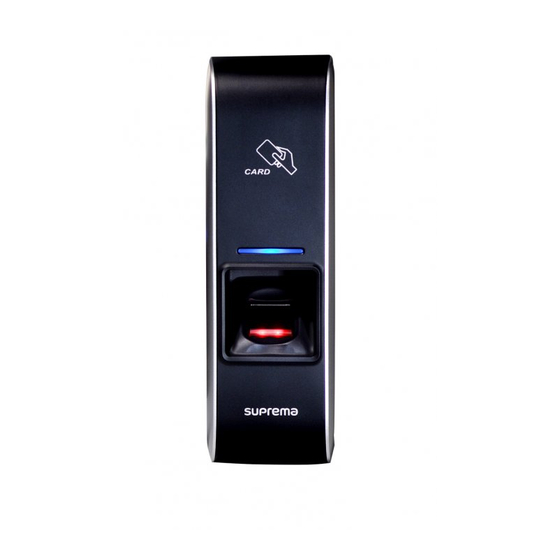
Page 5: Features
7-pin cable connector Connects the switch inputs and relay outputs. Sets the RS-485 termination resistor and resets the network settings. 1: If the termination resistor of BioEntry Plus is required, set to ON. • DIP switch 2: Resets the network settings to the default. For details, refer to the Resetting Network Set •... -
Page 6: Cables And Connectors
Getting Started Cables and connectors Power and RS-485 Name Color PWR +VDC PWR GND Black 485 GND Gray 485 TRXP Blue 485 TRXN Yellow TCP/IP Name Color RJ45 Pin number ENET TXP Yellow ENET TXN Green ENET RXP ENET RXN Black Wiegand input/output (switchable) Name... -
Page 7: How To Scan A Fingerprint
• Precautions for reading a fingerprint BioEntry Plus can read fingerprints regardless of the change in seasons or condition of the fingers. However, the external environment or the finger's placement can affect the recognition rate. If a fingerprint is not well read, the following actions are recommended. -
Page 8: Installation
With the mounting screws for the bracket, mount the bracket firmly onto the surface where BioEntry Plus is to be installed. NOTE • If BioEntry Plus should be installed onto a concrete wall, make a hole with a drill, and then insert a PVC anchor into the hole before screwing the mounting screw. Attach BioEntry Plus onto the mounted bracket. -
Page 9: Connecting To Power
If the power adapter is shared by other devices, the power adapter should provide a current more than the sum of the power consumption from this device (1,500 mA) and other devices. Use a separate power supply for Secure I/O 2, electric lock and BioEntry Plus respectively. If connecting and using the power supply •... -
Page 10: Connecting To A Network
TCP/IP connector (4-pin) BioEntry Plus LAN connection (connecting directly to a PC) BioEntry Plus can be connected directly to a PC by using a normal straight type CAT-5 cable because it supports an automatic MDI/MDIX function. TCP/IP connector (4-pin) BioEntry Plus... -
Page 11: Connecting To An Door Button/Door Sensor
2 - TTL GND Black 3 - TTL IN1 Green 4 - TTL GND Black Door sensor BioEntry Plus Door button Digital input connection (Alarm, Emergency switch) 1 - TTL IN0 Yellow 2 - TTL GND Black 3 - TTL IN1... -
Page 12: Connecting To A Relay
• Install the diode close to the door lock device. • Use a separate power source for BioEntry Plus from the door lock device. • Fail Secure Lock To use fail secure lock, connect N/O terminal as shown below. Normally, there is no current flowing through the relay and the door is opened when the relay is activated by a current flows. -
Page 13: Connecting To An Automatic Door
Sensor Automatic door controller Door Lock 7 - RLY NO White 6 - RLY COM Blue BioEntry Plus Connecting as a standalone 1 - TTL IN0 Yellow 2 - TTL GND Black 3 - TTL IN1 Green 4 - TTL GND... -
Page 14: Connecting To Secure I/O 2
If it is installed in the middle of the chain, the performance in communicating will deterior ate because it reduces the signal level. If the termination resistor of BioEntry Plus is required, set the #1 DIP switch to ON. -
Page 15: Resetting Network Settings
Installation Resetting Network Settings Turn the power off. Set DIP switch #2 to ON (right position). After turning on and then connect the device with default values. • TCP/IP address: DHCP address assignment (If DHCP address assignment is failed, 169.254.0.1 will be set.) •... -
Page 16: Product Specifications
Product Specifications Product Specifications Category Feature Specification Biometric Fingerprint 125KHz EM, 125KHz HID Prox, 13.56MHz Mifare/DESFire, 13.56MHz i Main RF Card CLASS Multi-Controller Max. User (1:1) 5,000 Max. User (1:N) 5,000 Capacity Max. Template (1:1) 10,000 (Two templates per finger) Max. -
Page 17: Dimensions
Product Specifications Dimensions (Unit: mm) Front view Side view Bracket... -
Page 18: Fcc Compliance Information
FCC Compliance Information FCC Compliance Information THIS DEVICE COMPLIES WITH PART 15 OF THE FCC RULES. Operation is subject to the following two conditions: (1) This device may not cause harmful interference, and (2) This device must accept any interference received, including interference that may cause undesired operation. Note: This equipment has been tested and found to comply with the limits for a Class B digital device, pursuant to part 15 of the FCC Rules. -
Page 19: Appendices
Suprema are exempt from liability even when it is claimed that there is a significant fault in the design or production process, and also they are not liable for any direct or indirect cost or expenditure including legal costs. - Page 20 Tel: +82 31 783 4502 I Fax: +82 31 783 4503 I Inquiry: sales@supremainc.com ©2018 Suprema Inc. Suprema and identifying product names and numbers herein are registered trade marks of Suprema, Inc. All non-Suprema brands and product names are trademarks or registered trademarks of their respective companies. Product appearance, build status and/or specifications are subject to change without notice.
Need help?
Do you have a question about the BioEntry Plus and is the answer not in the manual?
Questions and answers