
Related Manuals for suprema bioentry PLUS


Summary of Contents for suprema bioentry PLUS
- Page 1 IP based Fingerprint Access Control Installation Guide (ver 1.2) EN 101.00.BEP V1.22 www.supremainc.com...
-
Page 2: Table Of Contents
Bottom and Back Side Product Dimension Cables and Connectors Installation of Wall-mount Bracket Power Connection Ethernet Connection RS485 Connection Relay Connection Digital Input Connection Wiegand Output Network Default Setting Installation Reference Electrical Specification Troubleshooting Device cleaning FCC Rules Specifications ⒸCopyright 2007 Suprema Inc. -
Page 3: Safety Precautions
Be careful not to let liquid like Clean the device often to remove In cleaning, do not splash water dust on it. on the device but wipe it out with water, drinks or chemicals leak smooth cloth or towel. inside the device. ⒸCopyright 2007 Suprema Inc. - Page 4 Do not disassemble, repair or alter the device. Do not let children touch the Do not use the device for any Contact your nearest dealer in other purpose than specified. device without supervision. case of a trouble or problem. ⒸCopyright 2007 Suprema Inc.
-
Page 5: Basics Of Fingerprint Recognition
Fingerprint templates are saved inside the memory of BioStation and used for identification. Secure way to protect personal information To avoid privacy concern, Suprema’s fingerprint products do not save fingerprint images itself. It is impossible to reconstruct a fingerprint image from a fingerprint template which is just numeric data of the features of a fingerprint. -
Page 6: How To Place A Finger
How to place a finger Suprema’s fingerprint products show an outstanding recognition performance regardless of the user’s fingerprint skin condition or the way of fingerprint positioning. However, following tips are recommended to get more optimal fingerprint recognition performance. Select a finger to enroll ... - Page 7 How to place a finger Tips for different fingerprint conditions Suprema’s fingerprint products are designed to scan fingerprint smoothly regardless of the conditions of a finger skin. However, in case a fingerprint is not read well on the sensor, please refer to the followings tips.
-
Page 8: Product Contents
Basic Contents Diode (1 EA) Wall mounting screws – 2 ea Star-shaped screws Star-shaped small wrench Software CD 3 pin, 4 pin, 5 pin, 7 pin cables – each 1 ea BioEntry Plus Wall-mounting metal bracket ⒸCopyright 2007 Suprema Inc. -
Page 9: Optional Accessories
Product Contents Optional accessories Secure I/O 12V power adaptor Plastic stand USB fingerprint scanner for enrollment on PC ⒸCopyright 2007 Suprema Inc. -
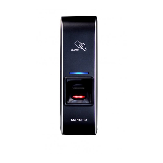
Page 10: Front Side
Fail Flicker Red Color per 2sec : Failed. Please Fingerprint sensing part contact to your distributor or Suprema Place a finger on a sensor surface Flicker Yellow Color per 2sec : Waiting Input Flicker Yellow Color per 1sec : Receiving IP ... -
Page 11: Bottom And Back Side
4 pin connector – ethernet (TCP/IP) 7 pin connector – digital input and relay output DIP switch : RS485 termination setting (Refer to “RS485 Connection” pages for details) Network default setting (Refer to “Network Default Setting” pages for details) ⒸCopyright 2007 Suprema Inc. -
Page 12: Product Dimension
Product Dimension Front Side Metal Bracket (unit : mm) ⒸCopyright 2007 Suprema Inc. -
Page 13: Cables And Connectors
WIEGAND DATA1 WHITE WIEGAND GND BLACK Digital Inputs and Relay output PIN DESCRIPTION WIRE SW1 INPUT YELLOW SW1 GND BLACK SW2 INPUT GREEN SW2 GND BLACK RELAY NORMAL CLOSE ORANGE RELAY COMMON BLUE RELAY NORMAL OPEN WHITE ⒸCopyright 2007 Suprema Inc. -
Page 14: Installation Of Wall-Mount Bracket
Installation of Wall-mount Bracket Fix wall mount bracket on a wall using wall mounting Hook BioEntry Plus on the wall mount bracket screws Wall mounting screws Fix BioStation and wall mounting bracket using a star shape screw. -
Page 15: Power Connection
(5) TRX- (Yellow) BioEntry Plus Recommended power supply 12V ± 10%, at least 500mA. Comply with standard IEC/EN 60950-1. To share the power with other devices, use a power supply with higher current ratings. ⒸCopyright 2007 Suprema Inc. -
Page 16: Ethernet Connection
Ethernet Connection ⒸCopyright 2007 Suprema Inc. - Page 17 Ethernet Connection (Direct connection with PC) To connect BioEntry Plus with a PC directly, connect both devices with a straight CAT-5 cable. As the BioEntry Plus supports auto MDI/MDIX feature, it is not necessary to use a crossover type cable. ⒸCopyright 2007 Suprema Inc.
-
Page 18: Rs485 Connection
RS485 Connection for Host Communication ⒸCopyright 2007 Suprema Inc. - Page 19 RS485 Connection for Secure I/O Max number of devices Maximum numbers of devices in an RS485 loop are two(2) devices (BioStation or BioEntry Plus) and four(4) Secure I/Os ⒸCopyright 2007 Suprema Inc.
-
Page 20: Relay Connection
Make sure to install the diode near to the door lock. • Make sure to use different power supplies for the BioEntry Plus and the door lock. • Make sure to install the diode at both ends of the circuit as shown in the figure above in order to protect the relay contact from the reverse current that occurs when the door lock works. - Page 21 Make sure to install the diode near to the door lock. • Make sure to use different power supplies for the BioEntry Plus and the door lock. • Make sure to install the diode at both ends of the circuit as shown in the figure above in order to protect the relay contact from the reverse current that occurs when the door lock works.
- Page 22 Relay Connection - Automatic door RTE Switch Presence Detector BioEntry Plus Automatic Door (7) Normally Open / N.O. (White) Door Controller (6) Common (Blue) (5) Normally Closed / N.C. (Orange) ⒸCopyright 2007 Suprema Inc.
-
Page 23: Digital Input Connection
Digital Input Connection (RTE, Door sensor) BioEntry Plus (4) SW1 GND (Black) (3) SW1 Input (Green) (2) SW0 GND (Black) (1) SW0 Input (Yellow) Door Status Request To Exit ⒸCopyright 2007 Suprema Inc. - Page 24 Digital Input Connection (Alarm, Emergency sw) BioEntry Plus (4) SW1 GND (Black) (3) SW1 Input (Green) (2) SW0 GND (Black) (1) SW0 Input (Yellow) Switch #1 Switch #0 ⒸCopyright 2007 Suprema Inc.
-
Page 25: Wiegand Input/Output
Wiegand Input/Output Wiegand Input Wiegand Output ⒸCopyright 2007 Suprema Inc. -
Page 26: How To Initialize Network Setting
In case of forgetting network setting of BioEntry Plus (TCP/IP or RS-485 setting) during installation or using BioEntry Plus, user can initialize network setting (TCP/IP or RS-485 setting) by using DIP SW installed on the back panel of BioEntry Plus. Please refer to the figures in below. -
Page 27: Installation Reference
Installation Reference 1 - Stand alone Door Sensor Exit Button Door Lock BioEntry Plus Enroll Scanner ⒸCopyright 2007 Suprema Inc. - Page 28 Installation Reference 2 – Secure RS485 Door Sensor Door Lock Exit Button Secure I/O BioEntry Plus Enroll Scanner ⒸCopyright 2007 Suprema Inc.
- Page 29 Installation Reference 3 – Network Door Zone 1 (Anti passback) RS485 RS485 BioStation BioEntry Plus BioEntry Plus Secure I/O PC Server Enroll Scanner PC Client Exit Button BioStation Secure I/O BioEntry Plus RS485 PC Client Door Zone 2 (Anti passback) ⒸCopyright 2007 Suprema Inc.
-
Page 30: Electrical Specification
The input ports are pulled up with 4.7k resistors TTL/Wiegand Output The outputs ports are open drain type, pulled up with 4.7k resistors Pull-up resistance (Ω) 4.7k internally Relay 30V DC Switching capacity (A) 125V AC Switching power (resistive) 37.5VA Switching voltage (V) ⒸCopyright 2007 Suprema Inc. -
Page 31: Troubleshooting
Check whether an antipass back mode is in use. In antipass back mode, only who entered can exit. Device doesn’t operate though power is connected. Check whether a device and a bracket is well connected to each other. If not, a tamper switch is activated and the device doesn’t work. ⒸCopyright 2007 Suprema Inc. -
Page 32: Device Cleaning
In case there is dust or impurities on the sensor of the BioStation, wipe off the surface with dry towel. Note that if the sensor is cleaned by detergent, benzene or thinner, surface is damaged and fingerprint can’t be entered. ⒸCopyright 2007 Suprema Inc. -
Page 33: Fcc Rules
Increase the separation between the equipment and receiver. Connect the equipment into an outlet on a circuit difference from that to which the receiver is connected. Consult the dealer or an experienced radio/TV technician for help ⒸCopyright 2007 Suprema Inc. -
Page 34: Specifications
125kHz EM card (EM4100) Card option 125kHz HID Proximity Card 13.56MHz Mifare Card Size 50 x 160 x 37 mm (Width x Height x Depth) Certified KCC, CE, FCC ⒸCopyright 2007 Suprema Inc. - Page 35 16F Parkview Office Tower, Jeongja-dong, Bundang-gu, Seongnam, Gyeonggi, 463-863 Korea E-mail : support@supremainc.com Website : www.supremainc.com Functions and specifications of the product are subject to changes without notice due to quality enhancement or function update. For any inquiry on the product, please contact Suprema Inc.
Need help?
Do you have a question about the bioentry PLUS and is the answer not in the manual?
Questions and answers