Table of Contents
Advertisement
Quick Links
Advertisement
Table of Contents

Related Manuals for suprema DM-20


Summary of Contents for suprema DM-20
- Page 1 Door Module INSTALLATION GUIDE Version 1.2 English EN 101.00.DM-20 V1.2A...
-
Page 2: Table Of Contents
CONTENTS Safety information Product Specifications Instructional icons FCC compliance information Introduction Components Appendices Name of each part Disclaimers Installation Example Copyright Notice Installation Mounting the Bracket Mounting the Support Boss Power connection RS-485 connection Fail Safe Lock Fail Secure Lock Wiegand Door button Door sensor... -
Page 3: Safety Information
Safety information Please read this safety instructions before you use the product to prevent injury to yourself and others and to prevent property damage. The term 'product' in this manual refers to the product and any items provided with the product. Instructional icons Warning: This symbol indicates situations that could result in death or severe injury. - Page 4 Safety information Caution Installation Do not install the power supply cable in a location where people pass by. • This may result in injury or product damage. Do not install the product near magnetic objects, such as a magnet, TV, monitor (especially CRT), or speaker. •...
-
Page 5: Introduction
Introduction Components Door Module Bracket Mounting PVC Anchors x4 Support Boss x4 120Ω resistor Diode x2 screws x4 • Components may vary according to the installation environment. -
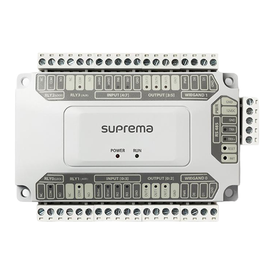
Page 6: Name Of Each Part
Input 0 ~ 3 (Includes Supervised Input) • Press INIT button to reset DM-20 interworking with a device and then connect to another device. • If you use the supervised input, refer to below details for LED status. - Orange: Open... -
Page 7: Installation Example
Introduction Installation Example DM-20 is connected with various I/O and Wiegand and can be compatible with 3rd party device. It can be used supervised input, a supervised connection is a four-state connection to determine if the connection is Open, Short, On, Off. -
Page 8: Installation
With the mounting screws for the bracket, mount the bracket firmly onto the surface where DM-20 is to be installed. • If DM-20 should be installed onto a concrete wall, make a hole with a drill, and then insert a PVC anchor into the hole before screwing the mounting screw. -
Page 9: Power Connection
• Up to 31 card readers or up to 7 fingerprint devices with 24 card readers can be connected with DM-20. (If Xpass set to master device, fingerprint devices cannot be connected as slave device.) Termination resistor (120Ω) -
Page 10: Fail Safe Lock
Installation Relay Fail Safe Lock In order to use the Fail Safe Lock, connect the N/C relay as shown in the figure below. There is normally a current flowing through the relay for the Fail Safe Lock. When the relay is activated, blocking the current flow, the door will open. If the power supply to the product is cut off due to a power failure or an external factor, the door will open. -
Page 11: Wiegand
Installation Wiegand If the power is shared by Wiegand devices, it is recommended to connect 12V and 2.5 A to DM-20. 3rd party device DC power (12V, 2.5A) You can use 12V, Max. 1.5A for Wiegand devices. If you connect a device that needs 1.0A to WIEGAND 0, •... -
Page 12: Door Button
Installation Door button IN0(SP), IN1(SP), IN4(SP), IN5(SP) terminals support the supervised input, and it operates always as N/C(normally closed). If you want to connect with non-supervised input, use IN2, IN3, IN6, IN7 terminals. RTE button Door button Door Door sensor IN0(SP), IN1(SP), IN4(SP), IN5(SP) terminals support the supervised input, and it operates always as N/C(normally closed). -
Page 13: Product Specifications
Product Specifications Category Feature Specification Model DM-20 Cortex M3 72 MHz Memory 128KB Flash, 20KB SRAM Multi-color • Power x1 • Relay x4 • TTL Input x4 • Supervised Input x4 • TTL Output x6 General • RS-485 x2 •... - Page 14 Product Specifications Dimensions (Unit: mm) * The tolerance is ±0.3 mm. 35.8 90.5...
-
Page 15: Fcc Compliance Information
• Modifications: Any modifications made to this device that are not approved by Suprema Inc. may void the authority granted to the user by the FCC to operate this equipment. -
Page 16: Appendices
Information in this document is provided in connection with Suprema products. • The right to use is acknowledged only for Suprema products included in the terms and conditions of use or sale for such products guaranteed by Suprema. No license, express or implied, by estoppel or otherwise, to any intellectual property is granted by this document. - Page 17 QR code. http://www.supremainc.com/en/about/contact-us.asp © 2021 Suprema Inc. Suprema and identifying product names and numbers herein are registered trade marks of Suprema, Inc. All non-Suprema brands and product names are trademarks or registered trademarks of their respective companies.
Need help?
Do you have a question about the DM-20 and is the answer not in the manual?
Questions and answers