Table of Contents
Advertisement
Available languages
Available languages
Quick Links
INSTALLATION AND OPERATING INSTRUCTIONS
555CFK Circulating Fan Kit
CSA approved for use only with:
Valor models 530 I, Retrofi re RF24DV and Madrona MF28
Note: This kit must be installed or serviced by a qualifi ed installer, service agency or the gas
supplier. These instructions are to be used in conjunction with the main installation instructions for
the above listed models.
WARNING: If the information in these instructions is not followed exactly, a fi re or explosion
may result causing property damage, personal injury or loss of life.
GROUNDING: This power supply must be installed and grounded in accordance with local codes,
or in the absence of local codes, with the current Canadian Electrical Code CSA C22.1. or in the
USA the National Electrical Code ANSI/NFPA70 latest edition.
Description of System
The models listed above have been designed to
accommodate the installation of an air circulation fan.
Operated by a variable speed control and a thermally
actuated switch, the fan is designed to boost the
natural convection through the heater; this may be a
desirable feature dependent on the fi replace location
and room layout.
The circulating fan may be installed before the heater
installation or as a retrofi t at a later date.
Operation
The fan is designed for automatic operation using a
thermal switch. It will take approximately 10-15 minutes
for the appliance to warm up and allow the switch to
activate the fan.
To operate the fan, rotate the speed control knob
clockwise from OFF to HIGH. Further rotation will
control the fan speed, once the automatic thermal
switch has been activated.
If the fi re is turned off , the fan will continue to operate
until the thermal switch cools, unless the speed control
is manually turned to the OFF position.
Should electrical power fail, the heater operation
will remain unaff ected.
4000510-06
Electrical Requirements
The fan kit requires a power supply of 120 Volts,
1 phase, 60 Hz. Full load current is less than 1 amp.
PLEASE LEAVE INSTALLATION
AND OPERATING INSTRUCTIONS
WITH THE HOMEOWNER.
© 2018, Miles Industries Ltd.
1
Advertisement
Table of Contents

Related Manuals for Valor 555CFK


Summary of Contents for Valor 555CFK
- Page 1 555CFK Circulating Fan Kit CSA approved for use only with: Valor models 530 I, Retrofi re RF24DV and Madrona MF28 Note: This kit must be installed or serviced by a qualifi ed installer, service agency or the gas supplier. These instructions are to be used in conjunction with the main installation instructions for the above listed models.
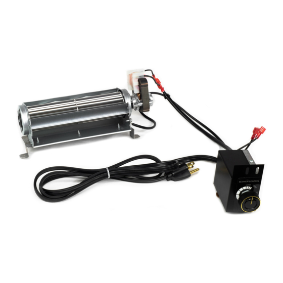
- Page 2 Fan Kit Components The complete #555CFK kit contains the following: • Fan & motor unit assembled to fan mounting bracket c/w wiring harness, speed control junction box, Fan with bracket mounted thermal sensor switch and 6’ cord set. • Control box mounting screw and cable retainer.
- Page 3 Installation with Valor Model Portrait 530 I 1. At the bottom right hand side of the fi rebox, raise 4. Fit the fan unit by placing it into the rear of the liner the sheet metal tab if not already raised.
- Page 4 Control Valve Fan Control Receiver (GV60) Installation with Valor Model Retrofi re RF24 (Direct Vent ONLY) 1. Remove the fan mounting bracket and reinstall in reverse position to the fan assembly. (The mounting bracket is originally supplied set up for heater model 530 application).
- Page 5 Installation with Valor Model Retrofi re RF24 (Direct Vent ONLY) 4. Fasten the fan control box to lower right hand support leg. (The control box may alternatively be fl ipped over and secured to the left hand support leg if desired.)
- Page 6 Installation with Valor Model Madrona MF28 1. Remove the mounting plate from the fan and 6. Fix the thermoswitch to the underside of the burner discard it. plate, behind the pilot area, with 2 screws taken from the burner plate.
-
Page 7: Maintenance
Miles Industries Ltd. warrants all components or lubrication; however, periodic cleaning of the unit of the model 555CFK Circulating Fan Kit for a compartment to remove household lint will help to period of one year from the date of purchase maintain peak performance and extend the fan life. -
Page 8: Exigences Électriques
Ventilateur pour circulation d’air 555CFK Homologué par la CSA pour usage exclusif avec les modèles de foyers Valor 530, Retrofi re RF24JD et Madrona MF28 Note : Ce kit doit être installé et entretenu par un installateur qualifi é, une agence de service certifi... -
Page 9: Contenu Du Kit
Contenu du kit Le kit 555CFK comprend les éléments suivants : Ventilateur et plaque de montage • Le ventilateur fi xé à la plaque de montage, le harnais de connexion, la boîte de contrôle de vitesses, l’interrupteur thermique et le cordon d’alimentation de 6 pieds. - Page 10 Installation sur le modèle Portrait 530 I 1. Soulevez la languette la plus à droite au fond sur la 4. Placez le ventilateur à l’arrière de la boîte de foyer paroi du fond de la boîte de foyer. (devant ses fi ls) et fi xez-le à la paroi arrière avec les deux vis fournies.
- Page 11 1. Dévissez la plaque de montage du ventilateur. Inversez-la et revissez-la dans les trous du bas. (La plaque de montage est fournie fi xée au ventilateur pour installation avec le foyer Valor 530.) Inversez la plaque et revissez-la dans les trous...
- Page 12 Installation sur le modèle Retrofi re RF24 (évent direct SEULEMENT) 4. Fixez la boîte de contrôle du ventilateur à la patte droite de la boîte du foyer. (La boîte de contrôle peut également être installée à la patte gauche du foyer, en position inverse.) Ventilateur fixé...
- Page 13 Installation sur le modèle Madrona MF28 1. Enlevez la plaque de montage fi xée au ventilateur 6. À l’aide de 2 vis tirées de la plaque du brûleur, fi xez et jetez-la. l’interrupteur thermique en-dessous de la plaque du brûleur, derrière l’emplacement de la veilleuse. Fixez l’interrupteur thermique au dessous de la plaque du brûleur à...
-
Page 14: Entretien
Ce ventilateur ne requiert pas d’entretien régulier ou Miles Industries Ltd. garantie toutes les pièces du de lubrifi cation. Cependant, un nettoyage périodique Ventilateur de circulation d’air 555CFK contre les du compartiment pour enlever la poussière accumulée défauts de matériaux ou de main-d’oeuvre pour aidera à...
Need help?
Do you have a question about the 555CFK and is the answer not in the manual?
Questions and answers