Table of Contents
Advertisement
Quick Links
Description
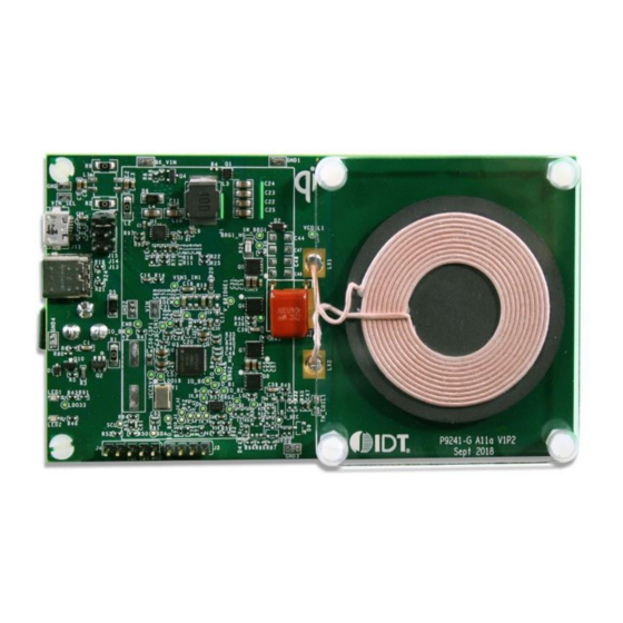
The P9241-G-EVK Evaluation Kit demonstrates the features of the
P9241-G 5 to 10W Wireless Power Transmitter (TX) with a fixed
frequency. It is intended to evaluate the functionality and perfor-
mance of the P9241-G when combined with a WPC Qi Baseline
Power Profile (BPP) power receiver in a wireless charging system
capable of providing 7.5W wireless charging for iPhone mode or
10W wireless charging for Android proprietary modes. The P9241-
G-EVK offers the flexibility to select parameters, such as the LED
pattern, power-loss foreign object detection (FOD) threshold, and
external temperature sensing function. The printed circuit board
(PCB) has four layers. It can be used with the user's WPC-1.2.4
compliant receiver.
The high-efficiency, turnkey reference design is supported by
comprehensive online, digital resources to significantly expedite
the design-in effort and enable rapid prototyping.
Contents for P9241-G-EVK Evaluation Kit
P9241-G-EVK Evaluation Board
© 2019 Integrated Device Technology, Inc.
P9241-G-EVK Evaluation Kit User Manual
Features
P9241-G Evaluation Board with support for WPC-1.2.4 BPP
receivers, such as IDT's P9225-R-EVK (sold separately)
Supports 7.5W wireless charging for iOS iPhones
Supports 10W wireless charging for Android phones
Adjustable power-loss FOD threshold
Adjustable temperature shutdown
Two programmable LED status indicators
Four-layer PCB
Fully assembled with test points and coil fixture
Kit Contents
P9241-G-EVK Evaluation Board
12V/2.0A QC3.0 Quick Charge USB Wall Charger
Micro-USB Cable
1
Micro-USB Cable
Quick Charge Wall Adaptor
12V/2.0A (Not to scale)
March 1, 2019
Advertisement
Table of Contents

Related Manuals for IDT P9241-G-EVK


Summary of Contents for IDT P9241-G-EVK
- Page 1 P9241-G-EVK Evaluation Kit User Manual Description Features The P9241-G-EVK Evaluation Kit demonstrates the features of the P9241-G Evaluation Board with support for WPC-1.2.4 BPP P9241-G 5 to 10W Wireless Power Transmitter (TX) with a fixed receivers, such as IDT’s P9225-R-EVK (sold separately) frequency.
-
Page 2: Table Of Contents
P9241-G-EVK Evaluation Kit User Manual Important Notes Disclaimer Integrated Device Technology, Inc. and its affiliated companies (herein referred to as “IDT”) shall not be liable for any damages arising out of defects resulting from delivered hardware or software (ii) non-observance of instructions contained in this manual and in any other documentation provided to user, or (iii) misuse, abuse, use under abnormal conditions, or alteration by anyone other than IDT. - Page 3 P9241-G-EVK Evaluation Kit User Manual P9241-G Evaluation Board Schematic ...............................13 Bill of Materials (BOM) ....................................14 Board Layout ......................................17 Ordering Information ....................................20 Revision History ......................................20 List of Figures Figure 1. P9241-G V1.2 Evaluation Board Features ............................4 Figure 2. P9241-G V1.2 Evaluation Board Details ..............................5 Figure 3.
-
Page 4: Hardware Setup
P9241-G-EVK Evaluation Kit User Manual 1. Hardware Setup Required or Recommended User Equipment The following additional lab equipment is required for using the kit: P9225-R-EVK Receiver Evaluation Board or any WPC-1.2.4 compliant receiver Power supply capable of 5V, 9V, 12V, 16V to 19V/1.8A or the 12V/2.0A QC3.0 Quick Charge USB Wall Charger with the Micro-USB Cable 2. -
Page 5: Figure 2. P9241-G V1.2 Evaluation Board Details
P9241-G-EVK Evaluation Kit User Manual Figure 2. P9241-G V1.2 Evaluation Board Details Buck IC Buck Power Stage Filter Buck Compensation Circuit Film Resonance Capacitor P9241-GB IC External Flash for Development High Voltage Input OVP Circuit External Crystal Note: The P9241-GB IC is used instead of the production P9241-G IC on the P9241-G V1.2 Evaluation Board. The P9241-G IC has firmware pre-programmed into the one-time programmable memory and does not allow users to customize the firmware. -
Page 6: Led Pattern Selection
LED Pattern Selection The P9241-G-EVK uses two LEDs (LED1 and LED2 (see Figure 1) to indicate the power transfer status, faults, and operating modes. The LEDs are connected to the LED1 and LED2 pins of the P9241-GB (see note below Figure 2) as shown in the P9241-G-EVK schematics. -
Page 7: External Temperature Sensing (Ts)
P9241-G-EVK Evaluation Kit User Manual Figure 3. R61 and R62 Location in the Schematic FOD AND LED PAT FOD_ADJ LDO33 LED_PAT Figure 4. R61 and R62 PCB Location External Temperature Sensing (TS) The P9241-G includes an optional temperature sense input pin, TS, that is used to monitor a remote temperature, such as for a coil or a battery charger. -
Page 8: External Buck Regulator
External Buck Regulator To operate at a fixed 127.7kHz frequency, the P9241-G-EVK has adopted an MP2229 buck IC to adjust the power transfer between the transmitter and receiver. GPIO_A4 and GPIO_B4 are assigned to adjust the MP2229 FB control. The MP2229 is operating at a fixed 500kHz frequency on the board. -
Page 9: Bypass Path Of The External Buck Regulator
Bypass Path of the External Buck Regulator When the adaptor voltage is 5V only (such as for USB DCP or legacy USB 5V adaptors), the P9241-G-EVK supports such adaptors by turning off the buck regulator and then enabling a bypass path. The P9241-G will be operating in a variable frequency mode to adjust the total power transferred. -
Page 10: External Crystal Circuit
P9241-G-EVK Evaluation Kit User Manual External Crystal Circuit To guarantee that the switching frequency is fixed at an accurate 127.7 kHz, two different types of crystals can be used to guarantee that the frequency will be in the range defined in Table 2. Only one crystal is necessary; a choice can be made between the crystals designated as Y1 and Y2 in Table 2 by comparing cost and package size. -
Page 11: Resonant Capacitor
Selection of Input Source and Operation Mode The P9241-G-EVK supports different types of AD/DC adaptors and connectors. A shunt on the jumpers identified in Figure 13 can be used to select the USB-Micro connector, USB-C connector, or DC jack adaptor. To select the proper jumper settings, refer to Figure 13. -
Page 12: Transmitter Coil
P9241-G-EVK Evaluation Kit User Manual The P9241-G-EVK supports a wide range of input DC sources from 5V to 19V. Based on the input source, the P9241-G-EVK supports different types of receivers. Table 4 lists the P9241-G-EVK operation modes. Table 4. -
Page 13: P9241-G Evaluation Board Schematic
P9241-G-EVK Evaluation Kit User Manual 3. P9241-G Evaluation Board Schematic © 2019 Integrated Device Technology, Inc. March 1, 2019... -
Page 14: Bill Of Materials (Bom)
P9241-G-EVK Evaluation Kit User Manual 4. Bill of Materials (BOM) Table 3. P9241-G-EVK BOM Item Reference Value Description Part Number Manufacturer Qty. 0.1µF CAP CER 0.1UF 25V X7R 0603 885012206071 Wurth Electronics Inc. C2, C7, C31, C32, C35, 10µF CAP CER 10UF 25V 20% X5R... - Page 15 P9241-G-EVK Evaluation Kit User Manual Item Reference Value Description Part Number Manufacturer Qty. SIP con 4 Positions Header, Unshrouded 961104-6404-AR Connector 0.100" (2.54mm) Through Hole Gold or Gold, GXT961104-6404-AR, sip-4 68000-105HLF BERGSTIK II .100" SR 68000-105HLF Amphenol ICC STRAIGHT, sip5...
- Page 16 P9241-G-EVK Evaluation Kit User Manual Item Reference Value Description Part Number Manufacturer Qty. 2.4kΩ RES SMD 2.4K OHM 1% 1/10W RC0603FR-072K4L Yageo 0603 R22, R25 10Ω RES SMD 10 OHM 1% 1/10W ERJ-2RKF10R0X Yageo 0402 200kΩ RES SMD 200K OHM 1% 1/10W...
-
Page 17: Board Layout
P9241-G-EVK Evaluation Kit User Manual 5. Board Layout Figure 14. Silkscreen – Top of Board © 2019 Integrated Device Technology, Inc. March 1, 2019... -
Page 18: Figure 15. Copper - Top Layer
P9241-G-EVK Evaluation Kit User Manual Figure 15. Copper – Top Layer Figure 16. Copper – L1 Layer © 2019 Integrated Device Technology, Inc. March 1, 2019... -
Page 19: Figure 17. Copper - L2 Layer
P9241-G-EVK Evaluation Kit User Manual Figure 17. Copper – L2 Layer Figure 18. Copper – Bottom Layer © 2019 Integrated Device Technology, Inc. March 1, 2019... -
Page 20: Ordering Information
The information contained herein is provided without representation or warranty of a ny kind, whether express or implied, including, but not limited to, the suitability of IDT's products for any particular purpose, an implied warranty of merchantability, or non -infringement of the intellectual property rights of others. This document is presented only as a guide and does not convey any license under intellectual property rights of IDT or any third parties.
Need help?
Do you have a question about the P9241-G-EVK and is the answer not in the manual?
Questions and answers