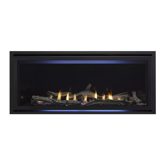
Advertisement
Quick Links
Leave this manual with party responsible for use and
operation.
CAUTION! Risk of Cuts or Abrasions. Wear protective
gloves and safety glasses during installation.
CAUTION: Logs are fragile, handle with care.
KIT COMPONENTS:
• Log Burner Assembly
• Ceramic Logs
COSMO32-IFT (4)
COSMO42-IFT (6)
SLR-X-AU (6)
• Glass Baffl e (COSMO42-IFT Only)
• Lava Rock (1 Bag)
• Mineral Wool (1 Bag)
• Instructions
INSTALLATION
1. Remove fi xed glass assembly by unlatching the top left
and right spring latches. Allow the fi xed glass assembly
to tilt away from the fi replace and lift the fi xed glass as-
sembly up and out of the opening.
2. Remove any existing media from appliance.
3. Remove the base pan assembly by removing two
screws located in front of the burner. Use your thumbs
and fi ngertips to grasp the front of the base pan and the
fl ange in the front of the burner respectively. Lift base
pan up and out.
4. Begin removal of the burner assembly by removing two
screws that secure the pilot hood to the bracket that is
attached to the burner. These screws are located on the
back side of the pilot hood. Once the screws are re-
moved, slide the pilot hood toward the back wall of the
fi rebox and lift out.
Remove the two screws that attach the pilot assembly
to the burner bracket. Remove the screw that fastens
the burner bracket to the valve plate. Remove burner
by sliding it to the left to disengage the orifi ce fl ex. See
Figure 1. Discard original burner and media material.
5. Adjust air shutter setting on new burner. See Table 1.
Heat & Glo • LOGS-COSMO32, LOGS-COSMO42 Installation Instructions • 2491-932 Rev. D • 12/17
LOGS-COSMO32, LOGS-COSMO42
MODELS: COSMO32-IFT, COSMO42-IFT, SLR-X-AU
Installation Instructions
REMOVE SCREWS
REMOVE SCREWS
SLIDE BURNER LEFT TO DISENGAGE
SLIDE BURNER LEFT TO DISENGAGE
Figure 1. Remove Pilot Screws
Note: The burner shutter gap is pre-set at the factory to
the "fully open" position and is to be fi eld adjusted at the
time of installation. Shutter settings referenced below are
set based on the minimum vent confi guration (one elbow
application). See appliance Installation Manual.
MODEL
GAS TYPE
COSMO32-IFT
COSMO32-IFT
PROPANE
COSMO42-IFT
COSMO42-IFT
PROPANE
SLR-X-AU
SLR-X-AU
PROPANE
SLR-X-AU
BUTANE
Table 1. Air Shutter Settings
6. Replace standard burner with log burner that is includ-
ed with log kit. Secure the burner bracket to the valve
plate with one screw. Reinstall pilot assembly with two
screws. Ensure all excess pilot wires are pushed back
down through grommet. Reinstall the pilot hood with two
screws. Place base pan in appliance. Reinstall the two
screws in front of the burner.
7. Bend tab "up" from basepan to 90 degrees:
COSMO42-IFT: Bend 9 tabs and bend air tab. See Fig-
ure 3.
SLR-X-AU: Bend 7 tabs. Do not bend the two right rear
tabs or the air tab. See Figure 3.
COSMO32-IFT: Bend 7 tabs. See Figure 16.
For LOGS-COSMO32, instructions continue on page 5.
SETTING
NG
1/8 in.
3/16 in.
NG
1/4 in.
5/16 in.
NG
1/2 in. (13 mm)
3/8 in. (10 mm)
5/8 in. (16 mm)
1
Advertisement

Subscribe to Our Youtube Channel
Summary of Contents for Heat & Glo LOGS-COSMO32
- Page 1 Figure 1. Discard original burner and media material. 5. Adjust air shutter setting on new burner. See Table 1. For LOGS-COSMO32, instructions continue on page 5. Heat & Glo • LOGS-COSMO32, LOGS-COSMO42 Installation Instructions • 2491-932 Rev. D • 12/17...
-
Page 2: Mineral Wool
SLR-X-AU: Install Log #2 by placing the cutout on the left side of log over the pilot shield. Pull log forward until it contacts the rear basepan lip. Note that the tabs are not used. Heat & Glo • LOGS-COSMO32, LOGS-COSMO42 Installation Instructions • 2491-932 Rev. D • 12/17... - Page 3 The other end of the log rests on the smooth area on Log #2 noted in Figure 8. See Figure LOG LOCATING TAB LOG LOCATING TAB Figure 9. Place Log #5 Heat & Glo • LOGS-COSMO32, LOGS-COSMO42 Installation Instructions • 2491-932 Rev. D • 12/17...
- Page 4 ROCK ROCK GLASS BAFFLE GLASS BAFFLE Figure 11. Properly Placed Lava Rock / Location for Mineral Wool Figure 14. Glass Baffl e Installed - Front View Heat & Glo • LOGS-COSMO32, LOGS-COSMO42 Installation Instructions • 2491-932 Rev. D • 12/17...
- Page 5 Log #6 should lean back and rest on Log #7. See Figure 18. Heat & Glo • LOGS-COSMO32, LOGS-COSMO42 Installation Instructions • 2491-932 Rev. D • 12/17...
- Page 6 For the location of your nearest Heat & Glo dealer, please visit www.heatnglo.com. Heat & Glo, a brand of Hearth & Home Technologies 7571 215th Street West, Lakeville, MN 55044 www.heatnglo.com Heat & Glo • LOGS-COSMO32, LOGS-COSMO42 Installation Instructions • 2491-932 Rev. D • 12/17...


Need help?
Do you have a question about the LOGS-COSMO32 and is the answer not in the manual?
Questions and answers