Advertisement
Quick Links
1.800.561.8187
DWYER INSTRUMENTS, INC.
P.O. BOX 373 • MICHIGAN CITY, IN 46360, U.S.A.
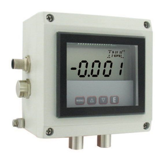
Series ISDP Intrinsically Safe Differential Pressure Transmitter
Specifications - Installation and Operating Instructions
www.
information@itm.com
.com
Phone: 219/879-8000
Fax: 219/872-9057
Bulletin A-25
www.dwyer-inst.com
e-mail: info@dwyermail.com
Advertisement

Subscribe to Our Youtube Channel
Related Manuals for Dwyer Instruments ISDP series


Summary of Contents for Dwyer Instruments ISDP series
- Page 1 Bulletin A-25 Series ISDP Intrinsically Safe Differential Pressure Transmitter Specifications - Installation and Operating Instructions 1.800.561.8187 information@itm.com www. .com DWYER INSTRUMENTS, INC. Phone: 219/879-8000 www.dwyer-inst.com P.O. BOX 373 • MICHIGAN CITY, IN 46360, U.S.A. Fax: 219/872-9057 e-mail: info@dwyermail.com...
- Page 2 DIMENSIONS 4-23/32 25/32 [120] [21.18] 4-9/64 3-7/16 [105.17] [87.12] BRACKETS ARE OPTIONAL 1-15/16 [48.97] 4-23/32 2-31/32 [120] [75.39] 5-7/32 [132.54] 1-45/64 1-17/32 1-5/16 [43.18] [38.61] 45/64 [33] [17.78] 4X ø3/16 [4.76] CLEARANCE Shown with Optional A-438 Mounting Bracket HOLES FOR MOUNTING MOUNTING HOLE 3-17/64 PATTERN...
-
Page 3: Specifications
SPECIFICATIONS Service: Air and non-corrosive gases. Wetted Materials: Ranges 5˝ and greater: glass, PVC, silicon, alumina ceramic, epoxy, RTV, gold, aluminum, stainless steel and nickel; Ranges 1˝ and lower: stainless steel, silicone, gold and ceramic. Housing Materials: Aluminum, glass. Accuracy: ±0.5% at 77°F (25°C) including hysteresis and repeatability (after 1 hour warm-up). -
Page 4: Wire Connection
M-12 Connector A-231 M-12 Cable Colors PIN 1 is Brown (positive) PIN 3 is Blue (negative) Use Model A-231 shielded cable with 4 pin Female M-12 connection. 2-WIRE CONNECTION POWER ISDP SUPPLY TRANSMITTER 10-35 VDC RECEIVER Fig. C -------2-Wire Operation- An external power supply delivering 10 - 35 VDC with minimum current capability of 40 mA DC (per transmitter) must be used to power the control loop. -
Page 5: Installation
INSTALLATION Mount the instrument in a location that will not be subject to excessive temperature, shock or vibration. Pressure Connections Use 1/8˝ male NPT fittings. When tightening fittings, grasp the brass fitting on the ISDP with a 1/2˝ wrench to prevent the fitting on the ISDP from turning. KEY FUNCTIONS HOME POSITION MAIN MENU... - Page 6 MENU MAP MENU MAP MENU MAP SETTINGS MAIN MENUS SUB MENUS MAIN MENUS SUB MENUS SETTINGS SETTINGS MENUS MENUS UNAVAILABLE UNAVAILABLE BI-DIRECTIONAL BI-DIRECTIONAL RANGES AND RANGES AND RANGES ABOVE RANGES ABOVE 25 IN. W.C. 25 IN. W.C. CONTINUED CONTINUED CONTINUED 1.800.561.8187 information@itm.com www.
- Page 7 CONTINUED CONTINUED CONTINUED MENU MENU 1.800.561.8187 information@itm.com www. .com...
- Page 8 SETTINGS MAIN MENUS SUB MENUS SETTINGS MAIN MENUS SUB MENUS Menus present only in pressure operation MENU MENU 1.800.561.8187 information@itm.com www. .com...
- Page 9 Model Chart Range Model 0-0.25˝ ISDP-002 0-1˝ WC ISDP-004 0-2.5˝ WC ISDP-005 0-5˝ WC ISDP-006 0-10˝ WC ISDP-007 0-25˝ WC IDSP-008 0-50˝ WC ISDP-009 0-100˝ WC ISDP-010 -0.1/+0.1˝ WC ISDP-011 -0.25/+0.25˝ WC ISDP-012 -0.5/+0.5˝ WC ISDP-013 -1.0/+1.0˝ WC ISDP-014 -2.5/+2.5˝ WC ISDP-015 -5.0/+5.0˝ WC ISDP-016 -10/+10˝ WC ISDP-017 Main Menu Selections (Upper Right Display Reads MENU ) Security - Lock out access to menus and settings.
- Page 10 MAIN MENUS and SUB MENUS SECr (Security) MAIN MENU SECr is the only SUB MENU in the security MENU. When the security SUB MENU is selected, the present security level is displayed in the upper right hand display. To change the security level, adjust the number displayed to the number shown in the following table for the desired security level.
- Page 11 PrES (Pressure) SUB MENU For pressure measurement, the following units are available: INWC - Inches of water column MMHG - Millimeters of mercury FTWC - Feet of water column MBAR - Millibar MMWC - Millimeters of water column PA - Pascal CMWC - Centimeters of water column KPA - Kilopascals PSI - Pounds per square inch...
- Page 12 FLO (Flow) SUB MENU For flow measurements the following units are available: SCFM - Standard cubic feet per minute M^3H - Cubic meters per hour FLO r (Flow Range) SUB MENU LO - 99.99 x 1K flow range HI - 999.9 x 1K flow range Tables 3 -6 show the flow ranges available, and the maximum duct size that can be set for each input range.
- Page 13 ArEA , DIA , XDIM and YDIM SUB MENUS These SUB MENUS become accessible if the instrument is set for flow. When measuring flow, the area of the duct must be specified. Tables 3 and 4 show the input range vs maximum flow and duct size.
- Page 14 rESO (Resolution) SUB MENU The Series ISDP Controller is capable of displaying four digits of resolution. However, at very low pressures the instability of the pressure may cause fluctuations in the least significant digit causing the least significant digit to be of little value.
- Page 15 ZERO and SPAN (Calibration of Zero and Span) SUB MENUS The lower display reads CAL in this mode. ZERO Calibration NOTE: For accurate calibration, DO NOT apply any pressure when performing this function. With the display reading ZERO , press the ENTER key. The upper display will blink. Press ENTER again to complete the zeroing of the instrument or press the MENU key to cancel.
- Page 16 1.800.561.8187 information@itm.com ©Copyright 2014 Dwyer Instruments, Inc. Printed in U.S.A. 12/14 FR# 19-443480-00 Rev. 3 www. .com DWYER INSTRUMENTS, INC. Phone: 219/879-8000 www.dwyer-inst.com P.O. BOX 373 • MICHIGAN CITY, IN 46360, U.S.A. Fax: 219/872-9057 e-mail: info@dwyermail.com...
Need help?
Do you have a question about the ISDP series and is the answer not in the manual?
Questions and answers