Table of Contents
Advertisement
Quick Links
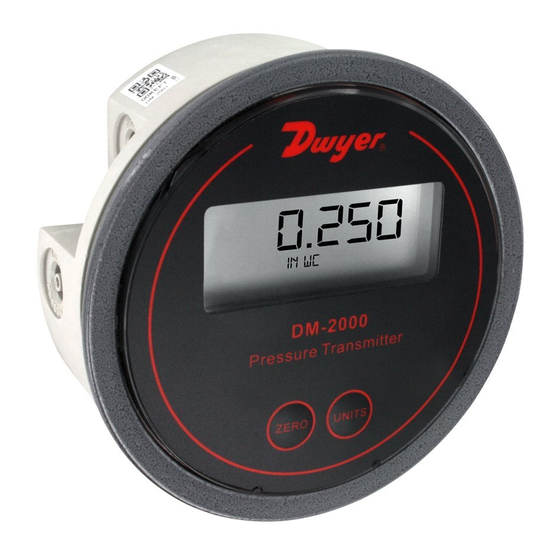
The Dwyer Series DM-2000 Differential Pressure Transmitter senses
the pressure of air and compatible gases and sends a standard 4-20 mA
output signal. The DM-2000 housing is specifically designed to mount in
the same diameter cutout as a standard Magnehelic
wide range of models are available factory calibrated to specific ranges.
Pressure connections are inherent to the glass filled plastic molded
housing making installation quick and easy. Digital push-button zero
simplifies calibration over typical turn-potentiometers. Single push button
allows field selection of 5 engineering units (LCD models only). An
optional 3.5 digit LCD shows process and engineering.
Accessories
Mounting Lugs
6-20 x 2˝ Screws - 3
6-19 x 1/2˝ Screws - 3
INSTALLATION
1. Location
Select a clean, dry mounting location free from excess vibration where
the temperature will remain between 20 and 120˚F (-6.7 and 48.9˚C).
Distance from the receiver is limited only by total loop resistance. See
Electrical Connections on next page. The tubing supplying pressure to
the instrument can be practically any length required, but long lengths
will increase response time slightly.
2. Position
A vertical position required. That is the position in which all standard
models are spanned and zeroed at the factory.
Pressure Connections
Two integral tubing connections are provided on the side of the gage.
They are sized to fit 1/8˝ (3.12 mm) I.D. tubing. Be sure the pressure
rating of the tubing exceeds that of the operating ranges.
Note: The tubing connections on the back of the gage are not to be used
as process connections.
3. Mounting
Panel - Provide a 4-9/16˝ diameter opening in panel. Insert gage and
secure in place with provided screws and adapters.
Surface - Provide three 3/16˝ diameter holes in panel on a 4-1/8˝
diameter bolt circle. Cut opening for terminal block as shown in diagram
to right.
DWYER INSTRUMENTS, INC.
1.800.561.8187
P.O. BOX 373 • MICHIGAN CITY, INDIANA 46360, U.S.A.
Series DM-2000 Differential Pressure Transmitter
Specifications – Installation and Operating Instructions
differential gage. A
®
www.
HIGH PRESSURE PORT
1-1/4
[31.75]
LOW PRESSURE PORT
7/16
[11.11]
17/32
[13.50]
1-11/16
[42.86]
SPECIFICATIONS
Service: Air and non-combustible, compatible gases.
Wetted Materials: Consult Factory.
Accuracy: ±1% F.S. at 70°F.
Stability: ±1% F.S./yr.
Temperature Limits: 20 to 120°F (-6.67 to 48.9°C).
Pressure Limits: 10 psig (0.69 bar).
Thermal Effect: ±0.055% F.S./°F (0.099% F.S./°C).
Power Requirements: 10-35 VDC (2 wire).
Output Signal: 4 to 20 mA.
Zero and Span Adjustments: Digital push-button zero and span.
Loop Resistance: DC: 0-1250 ohms maximum.
Current Consumption: DC: 38 mA maximum.
Electrical Connections: Screw-type terminal block.
Process Connections: 1/8˝ I.D. tubing.
Mounting Orientation: Vertical.
Weight: 4.8 oz (136 g).
Agency Approvals: CE.
Panel
Surface
11/16
(17.46)
1
(25.40)
1-1/2
(38.10)
Phone: 219/879-8000
Fax: 219/872-9057
information@itm.com
.com
Bulletin E-43-DM
ø4-3/4
[120.65]
5/32
[3.97]
65.000°
(3) HOLES FOR #6 SCREW
EQUALLY SPACED ON
4-1/8 (104.78) B.C.
www.dwyer-inst.com
e-mail: lit@dwyer-inst.com
Advertisement
Table of Contents

Related Manuals for Dwyer Instruments DM-2000


Summary of Contents for Dwyer Instruments DM-2000
- Page 1 4-20 mA Service: Air and non-combustible, compatible gases. output signal. The DM-2000 housing is specifically designed to mount in Wetted Materials: Consult Factory. the same diameter cutout as a standard Magnehelic differential gage.
- Page 2 1000 Vps–10.0 R Max. = 20mA DC Operating Region 10 13 15 Figure D ©Copyright 2013 Dwyer Instruments, Inc. Printed in U.S.A. 12/13 FR# 01-443402-00 Rev. 3 DWYER INSTRUMENTS, INC. Phone: 219/879-8000 www.dwyer-inst.com 1.800.561.8187 information@itm.com P.O. BOX 373 • MICHIGAN CITY, INDIANA 46360, U.S.A.
Need help?
Do you have a question about the DM-2000 and is the answer not in the manual?
Questions and answers