Advertisement
Table of Contents
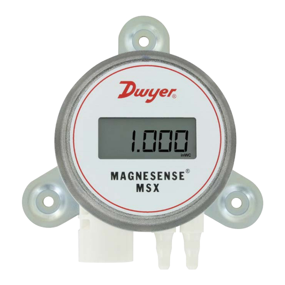
Series MSX Magnesense
Specifications - Installation and Operating Instructions
The Series MSX Magnesense
Differential Pressure Transmitter combines the
®
stability and versatility of the original Series MS2 Magnesense
in building control applications. The MSX simplifies the ordering process to deliver the
desired configuration, which reduces product setup time. Pressure ranges are available
in Pa, mm w.c., and in w.c. All pressure ranges can be configured in unidirectional or
bidirectional modes, providing a total of 32 ranges. The MSX transmitter can provide
a linear pressure output or a linear velocity output with the square root extraction from
the transmitter. Additional parameters have been included to expand the square root
capability to calculate flow. Dual voltage and milliamp output signals can be used to
provide both control and equipment output signal verification.
INSTALLATION
Surface Mounting:
Mount the transmitter on a vertical surface. The pressure sensor measurement
is unaffected by orientation, but it is recommended the unit be mounted with the
connections facing down to prevent moisture from entering either the pressure ports
or the electrical cable entry. Attach the mounting flange to a flat surface using #8 x 1/2˝
pan head sheet metal screws. Do not over tighten.
Duct Mounting (Universal model required):
Mount the transmitter away from fans, corners, heating and cooling coils and other
equipment that will affect the measurement of the pressure.
1. To mount the transmitter, drill a .562˝ (12.70 mm) diameter hole into the duct.
2. Screw duct probe into back of housing. Insert transmitter probe into the duct.
3. Mark location of mounting holes on duct using mounting flange as template. Drill
holes.
4. Attach mounting flange to duct with #8 x 1/2˝ pan head sheet metal screws. Do
not over tighten screws.
5. Place the included cap on the exterior positive pressure port.
The Universal model can also be used as a standard wall mount transmitter. In this
mode, do not use the duct probe and plug the port on the backside of the transmitter
with the included plug.
DWYER INSTRUMENTS, INC.
https://rodavigo.net/
II transmitter for use
®
Polígono Industrial O Rebullón s/n. 36416 - Mos - España - rodavigo@rodavigo.com
Polígono Industrial O Rebullón s/n. 36416 - Mos - España - rodavigo@rodavigo.com
Differential Pressure Transmitter
®
3-9/64
1/2 NPSM
[79.96]
1-31/32
[49.89]
1-3/16 [30.02]
Duct mount bracket
3-9/64
1/2 NPSM
[79.96]
1-29/32
[48.36]
1-3/16
[30.02]
13/32
1-43/64
[10.29]
[42.50]
DIN mount bracket
SPECIFICATIONS
Service: Air and non-combustible,
compatible gases.
Wetted Materials: Consult factory.
Accuracy: ±1% FSO.
Stability: ±1% FSO/year.
Temperature Limits: -4 to 158°F (-20
to 70°C).
Pressure Limits: Ranges 0 and 1: 3.6
psi max operation, 6 psi burst; Ranges 2
and 3: 6 psi max operation, 6 psi burst.
Power Requirements: 10-36 VDC
(2-wire), 17-36 VDC or isolated 21.6-33
VAC (3-wire).
Output Signals: 4-20 mA (2-wire); 0-10
V or 0-5 V selectable (3-wire).
Response Time: Instantaneous (default)
or 3 s (selectable).
Zero and Span Adjustments: Digital
push-button.
OPTIONS
Range
in w.c.
Pa low
Range 0
0.1
25
0.15
30
0.25
40
0.5*
50
Range 1
0.1
25
0.25
40
0.5
50
1*
60
Range 2
1
250
2
300
3
400
5*
500
Range 3
10
1000
15
1500
25
2000
28*
2500
*Indicated values are the positive full scale output values per range.
+34 986 288118
Servicio de Att. al Cliente
Bulletin P-MSX-A
1-1/16 [26.92]
33/64
2-3/32
[13.08]
[53.34]
11/32 [8.56]
[3] 3/16 [4.57] HOLES
Wall mount bracket
EQUALLY SPACED ON A
4-7/64 [104.53] BC
3/8 [9.53]
7-31/64 [190.12]
1-1/16 [26.92]
2-3/32
33/64 [13.08]
[53.34]
11/32
3-15/32
[8.56]
[88.19]
3-5/8
[92.08]
Loop Resistance: Current output:
0-1250 Ω max; Voltage output: min. load
resistance 1 k Ω.
Current Consumption: 21 mA max
continuous.
Electrical Connections: 4-wire
removable European style terminal block
for 16 to 26 AWG.
Electrical Entry: 1/2˝ NPS thread.
Display (optional): 4 digit LCD.
Process Connections: 1/8˝, 3/16˝, 1/4˝,
5 mm, and 6 mm ID flexible tubing.
Enclosure Rating: NEMA 4X (IP66); UL
2043 (Plenum); UL94 V-0.
Mounting Orientation: Pressure sensor
measurement unaffected by orientation.
Weight: 8.0 oz (230 g).
Agency Approvals: CE.
Pa high
mm w.c.
60
2.5
75
5
100
10
125*
12*
100
2.5
150
5
160
10
250*
25*
600
25
750
50
1000
100
1250*
125*
3000
250
4000
350
5000
500
7000*
700*
2-9/32
[57.79]
2-9/16
[64.96]
2-9/32
[57.79]
Advertisement
Table of Contents

Related Manuals for Dwyer Instruments Magnesense MSX Series


Summary of Contents for Dwyer Instruments Magnesense MSX Series
- Page 1 7000* 700* *Indicated values are the positive full scale output values per range. DWYER INSTRUMENTS, INC. Polígono Industrial O Rebullón s/n. 36416 - Mos - España - rodavigo@rodavigo.com Polígono Industrial O Rebullón s/n. 36416 - Mos - España - rodavigo@rodavigo.com...
- Page 2 https://rodavigo.net/ +34 986 288118 Servicio de Att. al Cliente ELECTRICAL 3-Wire 0-10 V and 0-5 V Voltage Output The MSX transmitter utilizes a 2-wire 4-20 mA Current Output, or a 3-wire 0-5 V CAUTION DO NOT EXCEED SPECIFIED SUPPLY VOLTAGE RATINGS. / 0-10 V Voltage Output.
-
Page 3: Dip Switch Settings
https://rodavigo.net/ +34 986 288118 Servicio de Att. al Cliente Simultaneous Current and Voltage Output Power Supply Refer to the following tables for the required supply rating. CAUTION DO NOT EXCEED SPECIFIED SUPPLY VOLTAGE RATINGS. PERMANENT DAMAGE NOT COVERED BY WARRANTY WILL Current Output RESULT. - Page 4 https://rodavigo.net/ +34 986 288118 Servicio de Att. al Cliente DIP Switch 3 - Pressure vs Velocity/Flow Mode of Operation DIP Switches 7 and 8 - Maximum Range Selection (Velocity/Flow) DIP Switch 3 toggles between pressure output vs velocity or flow output. DIP switches 7 and 8 work as a pair to select the maximum range output of the •...
-
Page 5: Lcd Display
https://rodavigo.net/ +34 986 288118 Servicio de Att. al Cliente LCD DISPLAY MAINTENANCE/REPAIR The LCD comes with a housing cover, which contains a window. The display plugs Upon final installation of the Series MSX, no routine maintenance is required. The into the pins on top of the circuit board. The LCD is 180° rotatable so that it will read Series MSX is not field serviceable and should be returned if repair is needed. - Page 6 https://rodavigo.net/ +34 986 288118 Servicio de Att. al Cliente MSX MAIN UI AND PRESSURE FLOWCHART MENU LEGEND PRESS ZERO/VALUE BUTTON HOLD ZERO/VALUE BUTTON PRESS SPAN/DIGIT BUTTON HOLD SPAN/DIGIT BUTTON POWER ON (RESET) PRESS EITHER ZERO/VALUE HOLD BOTH ZERO/VALUE OR SPAN/DIGIT BUTTON AND SPAN/DIGIT BUTTON DISPLAY ALL SEGMENTS...
- Page 7 https://rodavigo.net/ +34 986 288118 Servicio de Att. al Cliente MSX VELOCITY SETTINGS FLOWCHART MENU LEGEND PRESS ZERO/VALUE BUTTON HOLD ZERO/VALUE BUTTON PRESS SPAN/DIGIT BUTTON HOLD SPAN/DIGIT BUTTON HOLD BOTH ZERO/VALUE PRESS EITHER ZERO/VALUE AND SPAN/DIGIT BUTTON OR SPAN/DIGIT BUTTON VELOCITY MENU VELOCITY MENU (OUTPUT LOW MENU)
Need help?
Do you have a question about the Magnesense MSX Series and is the answer not in the manual?
Questions and answers