Table of Contents
Advertisement
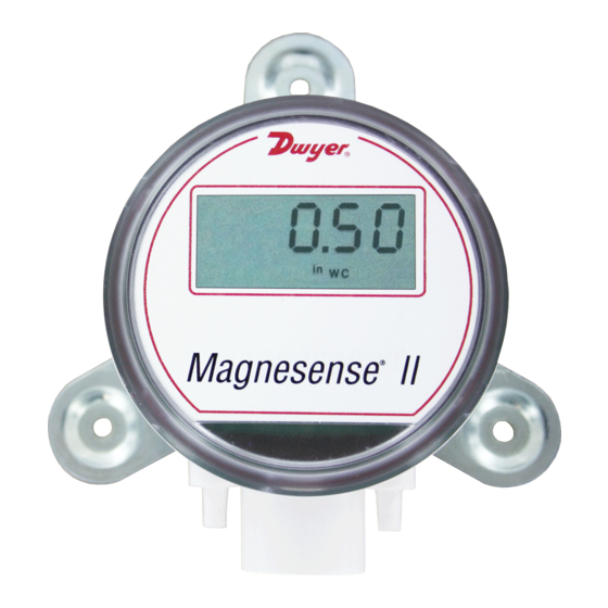
The Series MS2 Magnesense
®
BACnet Communication Protocol combines the proven stable Hall Effect
sensing technology of our original MS Series with additional features to reduce
installation time and simplify ordering. When using the pluggable integral display,
either Metric or English engineering units can be selected by changing the dip
switch position. A major benefit of the communications is the transmitters can be
daisy-chained together to reduce wiring time and installation cost. The
communications allow for the transmitter to integrate seamlessly into the existing
building automation control.
Like the original Series MS, the second generation transmitter can display pressure
or velocity with the square root extraction internal to the transmitter. Additional
parameters have been included to expand the square root capability to include flow
measurements.
INSTALLATION
Surface Mount:
The transmitter should be mounted on a vertical surface with the connections
directed down to prevent moisture from entering either the pressure ports or the
electrical cable entry. The diaphragm must be vertical to minimize gravity effects on
the diaphragm. Attach the mounting flange to a flat surface using three #8 x 1/2˝
pan head sheet metal screws. Do not over tighten.
Duct Mount:
The transmitter should be mounted away from fans, corners, heating and cooling
coils and other equipment that will affect the measurement of the pressure.
1. To mount the transmitter, drill a 9/16˝ (12.70 mm) diameter hole into the duct.
2. Insert transmitter probe into the duct.
3. Mark location of three mounting holes on duct using mounting flange as
template. Drill holes.
4. Attach mounting flange to duct with three #8 x 1/2˝ pan head sheet metal
screws. Do not over tighten screws.
DWYeR INSTRUMeNTS, INC.
P.O. BOX 373 • MICHIGAN CITY, INDIANA 46360, U.S.A.
Series MS2 Magnesense
with BACnet Communication
Specifications - Installation and Operating Instructions
II Differential Pressure Transmitter with
II Differential Pressure Transmitter
®
21/32
ø3-7/16
[16.55]
[ø87.31]
1/2 NPT
2-41/64
[67.16]
15/64
[6.00]
7-41/64[194.06]
Duct Mount Bracket
21/32
[16.51]
ø3-7/16
[ø87.31]
1/2 NPT
2-41/64
[67.24]
25/64
1-41/64
[9.97]
[41.71]
DIN Mount Bracket
SPeCIfICATIONS
Service: Air and non-combustible, compatible gases.
Wetted Materials: Consult factory.
Accuracy: ±1% FS for 0.25˝ (50 Pa), 0.5˝ (100 Pa), 2˝ (500 Pa), 5˝ (1250 Pa),
10˝ (2 kPa), 15˝ (3 kPa), 25˝ (5 kPa); ±2% FS for 0.1˝ (25 Pa), 1˝ (250 Pa), and
all bi-directional ranges.
Stability: ±1% / year FSO.
Temperature Limits: 0 to 150°F (-18 to 66°C).
Pressure Limits: 1 psi max., operation; 10 psi burst.
Power Requirements: 10 to 36 VDC or isolated 21.6 to 33 VAC.
Output Signals: BACnet MS/TP communication protocol.
Response Time: Averaging, adj 0 to 240 s.
Zero & Span Adjustments: Digital push buttons.
Current Consumption: 40 mA max.
Display (optional): 5-digit LCD.
electrical Connections: 5-wire terminal block, 18 to 24 AWG.
electrical entry: 1/2˝ NPS thread; Accessory (A-151): Cable gland for 5 to 10
mm diameter cable.
Process Connection: 3/16˝ ID tubing (5 mm ID); Max. OD 9 mm.
enclosure Rating: NEMA 4X (IP66).
Mounting Orientation: Diaphragm in vertical position.
Weight: 8.0 oz (230 g).
Agency Approvals: CE.
Phone: 219/879-8000
fax: 219/872-9057
Bulletin P-MS2-B
21/32
[16.55]
29/32
[23.02]
2-11/64
[55.25]
1/2
[12.77]
2-9/16
[65.12]
57/64
[22.67]
Wall Mount Bracket
[3] 3/16 [4.76] HOLES
EQUALLY SPACED ON A
4.115 [104.52] B.C.
29/32
21/32
[23.02]
2-11/64
[16.51]
[55.12]
1/2
[12.76]
57/64
[22.60]
www.dwyer-inst.com
e-mail: info@dwyermail.com
3-11/32
[84.84]
3-1/2
[88.90]
Advertisement
Table of Contents

Related Manuals for Dwyer Instruments Magnesense II MS2


Summary of Contents for Dwyer Instruments Magnesense II MS2
- Page 1 3. Mark location of three mounting holes on duct using mounting flange as template. Drill holes. 4. Attach mounting flange to duct with three #8 x 1/2˝ pan head sheet metal screws. Do not over tighten screws. DWYeR INSTRUMeNTS, INC. Phone: 219/879-8000 www.dwyer-inst.com P.O. BOX 373 • MICHIGAN CITY, INDIANA 46360, U.S.A.
- Page 2 electrical Wiring Dip Switch Configurations NOTICe Wiring should comply with Electrical Characteristics of Generators and Receivers for Use in Balanced Digital Multipoint Systems, TIA/EIA-485-A-1998, Telecommunications Industry Association, 1998. NOTICe Wiring should comply with ANSI/ASHRAE Standard 135-2010 BACnet A Data Communication Protocol for Building Automation and Control Networks, American Society of Heating, Refrigerating and figure 3 Air-Conditioning Engineers, Inc., 2010.
-
Page 3: Programming Menus
Zero Calibration PROGRAMMING MeNUS The zero calibration can be set by applying zero pressure to both the pressure ports and pressing the zero button for 3 seconds. If the local LCD is present, the display Home Menu will read S e r o and then sequence back to the home display. During normal operation, the display will be in the Home Menu and will display the current measured pressure and the engineering units. -
Page 4: Maintenance & Repair
BACnet Communication Protocol Object Overview Span Calibration The device supports the following objects In order to adjust the span calibration, apply pressure to the ports of the transmitter Object Dynamically Dynamically Object Object that is associated with the maximum end of the transmitter range. The binary value Type Creatable Deletable... -
Page 5: Appendix I: Setting Bacnet Communication Protocol Ms/Tp Mac Address Of Unit Switch Position 1
BACnetDeviceStatus Read of the dip switches, except position 1, in the ON position as shown in Figure 6 Vendor Name “Dwyer Instruments, Inc.” CharacterString Read below. The address of the transmitter would be 127 as it would be Vendor Identifier... -
Page 6: Appendix Iii: Analog Input Object Property Table
Appendix III: Analog Input Object Property Table Default Property Data Property Value Type Access Object Identifier BACnetObjectIdentifier Read Object Name Pressure inWC CharacterString Read Object Type ANALOG_INPUT (0) BACnetObjectType Read Present Value Current reading Real Read Status Flags BACnetStatusFlags Read Event State NORMAL (0) BACnetEventState... -
Page 7: Appendix Iv: Analog Value Object Property Table
Appendix IV: Analog Value Object Property Table Default Property Data Default Property Data Property Value Type Access Property Value Type Access Object Identifier BACnetObjectIdentifier Read Object Identifier BACnetObjectIdentifier Read Object Name Velocity FPM CharacterString Read Object Name Flow Area SqFt CharacterString Read Object Type... -
Page 8: Appendix V: Binary Value Object Property Table
Appendix V: Binary Value Object Property Table Default Property Data Property Value Type Access Object Identifier BACnetObjectIdentifier Read Object Name Use Default K Value CharacterString Read Object Type BINARY_VALUE (5) BACnetObjectType Read Present Value ACTIVE (1) BACnetBinaryPV Read/Write Status Flags BACnetStatusFlags Read Event State... -
Page 9: Appendix Vi: Menu Flow Chart
Appendix VI: Menu flow Chart BUTTON BUTTON PRESS PRESS LEGEND LEGEND PRESS PRESS ZERO ZERO BUTTON BUTTON ZERO ZERO PRESS PRESS SPAN SPAN BUTTON BUTTON SPAN SPAN PRESS PRESS AND AND HOLD HOLD ZERO ZERO BUTTON BUTTON ZERO ZERO PRESS PRESS AND AND HOLD HOLD SPAN SPAN BUTTON... - Page 10 PRESSURE PRESSURE MODE MODE MENU MENU FROM FROM AVERAGING AVERAGING MENU MENU ADJUST ADJUST PRESSURE PRESSURE OUTPUT OUTPUT HIGH HIGH " " AdJ P P FROM FROM MENUS MENUS SPAN SPAN DIP SWITCH SWITCH FULL FULL SCALE SCALE SETTING SETTING UPON UPON RELEASE RELEASE...
-
Page 11: Home Position
FLOW FLOW MODE MODE MENU MENU FROM FROM AVERAGING AVERAGING MENU MENU UNITS UNITS SELECTED SELECTED Unit Unit Unit Unit SELECTED SELECTED UNITS UNITS BY DIP DIP SWITCH SWITCH DISPLAYED DISPLAYED SETTING SETTING SPAN d1000 d1000 diSP diSP ADJUST ADJUST DISPLAY DISPLAY UPON UPON RELEASE... - Page 12 ©Copyright 2015 Dwyer Instruments, Inc. Printed in U.S.A. 7/15 FR# 444021-10 Rev. 3 DWYeR INSTRUMeNTS, INC. Phone: 219/879-8000 www.dwyer-inst.com P.O. BOX 373 • MICHIGAN CITY, INDIANA 46360, U.S.A. fax: 219/872-9057 e-mail: info@dwyermail.com...
Need help?
Do you have a question about the Magnesense II MS2 and is the answer not in the manual?
Questions and answers