Advertisement
Quick Links
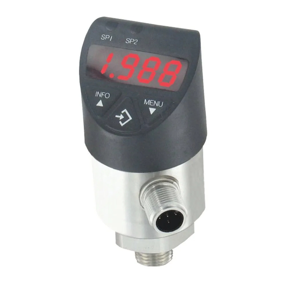
The Series DPT Digital Pressure Transmitter with Switches combines a large,
14-segment LED display with two programmable solid state switches into one
compact unit. A unique, 3-way rotating design allows the DPT to meet specific
installation requirements without any retrofitting. The display and electrical
connection can be rotated independently to maximize visibility while still orienting
the electrical connection in the best position for the cable connector. Large,
ergonomically designed push buttons allow for quick/easy programming and thin-
film piezoresitive sensor technology guarantees long-term reliability and stability.
INSTALLATION
When installing gage always use a hex at the base of the housing to tighten the
gage to a mating fitting. Do not apply wrench to housing.
POWER UP
4-digit LED display
1. LED (red)
2. LED (red)
Operating Modes
System start
Display Mode
Programming Mode
UNITS CHART
Range
Maximum Pressure
Model
(psig)
(psig)
DPT-V00
DPT-A00
-14.5 to 0
30
DPT-V01
DPT-A01
0 to 15
30
DPT-V02
DPT-A02
0 to 25
60
DPT-V03
DPT-A03
0 to 30
60
DPT-V04
DPT-A04
0 to 50
100
DPT-V05
DPT-A05
0 to 100
200
DPT-V06
DPT-A06
0 to 160
290
DPT-V07
DPT-A07
0 to 200
400
DPT-V08
DPT-A08
0 to 300
600
DPT-V09
DPT-A09
0 to 500
1000
DPT-V10
DPT-A10
0 to 1000
1740
*feet of seawater @ 4°C
DWYER INSTRUMENTS, INC.
P.O. BOX 373 • MICHIGAN CITY, INDIANA 46361, U.S.A.
Series DPT Digital Pressure Transmitter with Switches
Specifications - Installation and Operating Instructions
- Display system pressure
- Display Menu Item
- Display Parameter
- Status Switch Output 1
- Status Switch Output 2 (Optional)
- Display is fully activated for 2s
-When the pressure switch is powered up within
the range of the hysteresis, the output switch is
set to "not active" by default
- Normal operation, displays system pressure
- Setting Parameters
Burst Pressure
(psig)
bar
75
1.034
75
1.034
150
1.724
150
2.068
250
3.447
500
6.895
500
11.03
1500
13.79
1500
20.68
2500
34.47
7975
68.95
1-5/32
[29.50]
SPECIFICATIONS
Service: Compatible gases, liquids or vapors.
Wetted Materials:
Pressure connection: 316 L SS;
Pressure sensor: 316 L SS (13-8 PH for ranges above 150 psi).
Housing: 316 L SS lower body, heat and chemical resistant fiberglass reinforced
plastic (PBT) plastic head, TPE-E keyboard, PC display window.
Accuracy: 1.0% F.S. (includes non-linearity, hysteresis, zero point).
Pressure Limit: See table.
Temperature Limits: 32 to 176°F (0 to 80°C).
Process Connections: 1/4˝ male NPT.
Display: Red LED 4-digit (0.35˝ H digits).
Weight: 7 oz (0.2 kg).
SWITCH SPECIFICATIONS
Switch Type: PNP.
Electrical Rating: 250 mA.
Electrical Connections: M 12x1, 5-pin.
Mounting Orientation: Mount in any position.
TRANSMITTER SPECIFICATIONS
Temperature Limits: 32 to 176°F (0 to 80°C).
Thermal Effect: 0.2% FS / 10k.
Power Requirements: 15 to 35 VDC.
Output Signal: DPT-A: 4 to 20 mA; DPT-V: 0 to 10 VDC.
Loop Resistance: DPT-A: ≤ 0.5k; DPT-V: > 10k.
Power Consumption: ≤ 100 mA.
Electrical Connections: M 12x1, 5-pin.
Enclosure Rating: IP65 and IP67.
Agency Approvals: CE.
Pressure Ranges
2
MPa
kPa
kg/cm
.1034
103.4
1.055
.1034
103.4
1.055
.1724
172.4
1.758
.2068
206.8
2.109
.3447
344.7
3.515
.6895
689.5
7.031
1.103
1103
11.25
1.378
1378
14.06
2.068
2068
21.09
3.447
3447
35.15
6.895
6895
70.31
Phone: 219/879-8000
Fax: 219/872-9057
Bulletin P-DPT
1-1/2
[38.00]
3-23/64
[85.40]
1-33/64
[38.60]
www.dwyer-inst.com
e-mail: info@dwyer-inst.com
Advertisement

Related Manuals for Dwyer Instruments DPT series


Summary of Contents for Dwyer Instruments DPT series
- Page 1 2500 34.47 3.447 3447 35.15 DPT-V10 DPT-A10 0 to 1000 1740 7975 68.95 6.895 6895 70.31 *feet of seawater @ 4°C DWYER INSTRUMENTS, INC. Phone: 219/879-8000 www.dwyer-inst.com P.O. BOX 373 • MICHIGAN CITY, INDIANA 46361, U.S.A. Fax: 219/872-9057 e-mail: info@dwyer-inst.com...
- Page 2 WIRING Circular connector M12x1, 5-pin 2 switching outputs + 1 analogue output 0-10 V or 4-20 mA + = 1 - = 3 SP1 = 4 SP2 = 2 PROGRAMMING Menu (Programming and Factory Setting) Display-Mode Long press on Menu Key Programming-Mode Factory Setting: SP1 / FH1...
- Page 3 BUTTON OPERATION Display-Mode Programming-Mode short press: short press: INFO Display units - Menu up - Increase parameter value long press: long press: Run-through Parameter Info - Menu up 1. UNIT + unit - Increase parameter value 2. SP1 / FH1 + value 3.
- Page 4 Be sure to include a brief description of the problem plus any relevant application notes. Contact customer service to receive a returns goods authorization number before shipping. 11609185.01 10/2010 ©Copyright 2010 Dwyer Instruments, Inc. Printed in U.S.A. 10/10 FR# RA-443873-00 Rev. 1 DWYER INSTRUMENTS, INC. Phone: 219/879-8000 www.dwyer-inst.com...
Need help?
Do you have a question about the DPT series and is the answer not in the manual?
Questions and answers