Table of Contents
Advertisement
Quick Links
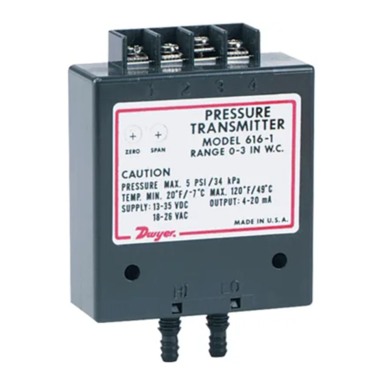
The Series 616 Differential Pressure Transmitter senses the pressure
of air and compatible gases and sends a standard 4-20 mA output
signal. A wide range of models are available factory calibrated to specific
ranges as listed in the chart below. The span and zero controls are for
use when checking calibration. They are not intended for re-ranging to a
significantly different span. Versatile circuit design enables operation in
2, 3 or 4-wire current loops.
For applications requiring direct pressure readings or percent of full span
output, the optional Model A-701 Digital Readout makes an ideal
companion device. It provides a bright red 0.6˝ high, 3-1/2 digit LED
display while supplying power to the Series 616 transmitter. For
additional information on these and other transmitters, see the Dwyer
Instruments, Inc. Full Line catalog.
Series 616 Transmitter Models and Ranges*
Model Range
616-00 0-1 in. w.c.
616-0
0-2 in. w.c.
616-1
0-3 in. w.c.
616-2
0-6 in. w.c.
616-3
0-10 in. w.c. 5 psig
616-4
0-20 in. w.c. 11 psig
616-5
0-40 in. w.c. 11 psig
616-6
0-100 in. w.c. 29 psig
616-7
0-200 in. w.c. 29 psig
*All models available with 0.25% F.S. Accuracy.
Models available with 1.0% F.S. Accuracy include 616-1 through 616-20B.
DWYER INSTRUMENTS, INC.
P.O. BOX 373 • MICHIGAN CITY, INDIANA 46361, U.S.A.
1.800.561.8187
Series 616 Differential Pressure Transmitter
Specifications – Installation and Operating Instructions
Max. Press. Model
Range
2 psig
616-8
0-10 psid
2 psig
616-9
0-20 psid
2 psig
616-10
0-30 psid
5 psig
616-11
0-50 psid
616-12
0-100 psid
616-3B
1.5-0-1.5 in. w.c. 2 psig
616-6B
3-0-3 in. w.c.
616-10B 5-0-5 in. w.c.
616-20B 10-0-10 in. w.c. 11 psig
www.
ø5/32 [3.97]
MOUNTING HOLE
TYP 2 PLACES
SPECIFICATIONS
Service: Air and non-combustible, compatible gases.
Wetted Materials: Consult factory.
Accuracy: 616: ±0.25% F.S.; 616C: ±1.0% F.S.
Stability: ± 1% F.S./yr.
Temperature Limits: 20 to 120°F (-6.67 to 48.9°C).
Pressure Limits: See Chart.
Thermal Effect: 616: ±0.055% F.S./°F (0.099% F.S./°C); 616C:
±0.070% F.S./°F (0.125% F.S./°C).
Power Requirements: 10-35 VDC (2, 3 or 4 wire); 16-26 VAC (4 wire).
Output Signal: 4 to 20 mA.
Zero and Span Adjustments: Potentiometers for zero and span.
Loop Resistance: DC: 0-1250 ohms maximum; AC: 0-1200 ohms
maximum.
Current Consumption: DC: 38 mA maximum; AC: 76 mA maximum.
Electrical Connections: Screw-type terminal block.
Process Connections: Barbed, dual size to fit 1/8˝ and 3/16˝
(3.12 mm and 4.76 mm) I.D. rubber or vinyl tubing.
Mounting Orientation: Vertical, consult factory for other position
orientations.
Weight: 1.8 oz. (51 grams).
Max. Press.
29 psig
58 psig
58 psig
150 psig
150 psig
5 psig
5 psig
Phone: 219/879-8000
Fax: 219/872-9057
.com
5/16
[7.950]
3-21/64
[84.53]
2-13/32
[61.12]
1/2
HI
LO
[12.70]
1/2
[12.70]
1-1/2
[38.10]
2-1/4
[57.15]
www.dwyer-inst.com
e-mail: lit@dwyer-inst.com
information@itm.com
Bulletin E-43
7/8
[22.23]
Advertisement
Table of Contents

Related Manuals for Dwyer Instruments Series 616


Summary of Contents for Dwyer Instruments Series 616
- Page 1 It provides a bright red 0.6˝ high, 3-1/2 digit LED Zero and Span Adjustments: Potentiometers for zero and span. display while supplying power to the Series 616 transmitter. For Loop Resistance: DC: 0-1250 ohms maximum; AC: 0-1200 ohms additional information on these and other transmitters, see the Dwyer maximum.
- Page 2 Installation 2-Wire Operation An external power supply delivering 10-35 VDC with minimum current 1.0 Location capability of 40 mA DC (per transmitter) must be used to power the Select a clean, dry mounting location free from excess vibration where control loop. See Fig. C for connection of the power supply, transmitter the temperature will remain between 20 and 120˚F (-6.7 and 48.9˚C).
- Page 3 Figure H Figure G Calibration Check Each Series 616 Transmitter is factory calibrated to the range given in the model chart. To check calibration and adjust if necessary, the following procedure should be used. For purposes of clarification in these instructions, range is defined as that pressure which, applied to the transmitter, produces 20 milliamps of current in the loop.
- Page 4 Multiple Receiver Installation An advantage of the standard 4-20 mA DC output signal produced by the Series 616 Transmitter is that any number of receivers can be connected in series in the current loop. Thus, an A-701 Digital Readout, an analog panel meter, a chart recorder, process controlling equipment or any combination of these devices can be operated simultaneously.
Need help?
Do you have a question about the Series 616 and is the answer not in the manual?
Questions and answers