CM Lodestar A Operating, Maintenance & Parts Manual
Hide thumbs
Also See for Lodestar A:
- Operating, maintenance & parts manual (94 pages) ,
- Operating, maintenance & parts manual (140 pages)
Table of Contents
Advertisement
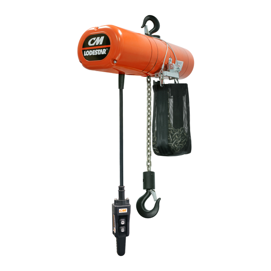
OPERATING, MAINTENANCE
& PARTS MANUAL
ELECTRIC CHAIN HOIST
Before installing hoist, fi ll in the information below.
Model Number
Serial No.
Purchase Date
Voltage
Rated Load
RATED LOADS 1/8 TO 3 TONNES
125 KG TO 3000 KG
Follow all instructions and warning for inspecting,
maintaining and operating this hoist.
The use of any hoist presents some risk of personal injury
or property damage. That risk is greatly increased if proper
instructions and warnings are not followed. Before using
this hoist, each operator should become thoroughly familiar
with all warnings, instructions and recommendations in this
manual. Retain this manual for future reference and use.
Forward this manual to operator. Failure to operate equipment
as directed in manual may cause injury.
Distributed by Ergonomic Partners
Sales@ErgonomicPartners.com
www.ErgonomicPartners.com
Tel: (314) 884-8884
P/N: 00001996 (REV AC) 627NH October 2014
Advertisement
Table of Contents

Related Manuals for CM Lodestar A


Summary of Contents for CM Lodestar A
- Page 1 OPERATING, MAINTENANCE & PARTS MANUAL ELECTRIC CHAIN HOIST Before installing hoist, fi ll in the information below. Model Number Serial No. Purchase Date Voltage Rated Load RATED LOADS 1/8 TO 3 TONNES 125 KG TO 3000 KG Follow all instructions and warning for inspecting, maintaining and operating this hoist.
- Page 2 CM HOIST PARTS AND SERVICES ARE AVAILABLE IN THE UNITED STATES AND IN CANADA PARTS FOR YOUR HOIST ARE AVAILABLE FROM YOUR LOCAL AUTHORIZED REPAIR STATION. 00001996 (REV AC) 627NH October 2014...
-
Page 3: Safety Precautions
A17.1). Columbus McKinnon Corporation cannot be responsible for 21. NOT remove or obscure the warnings on the hoist. applications other than those for which CM equipment is intended. 22. NOT operate a hoist on which the safety placards or decals are *Copies of this standard can be obtained from ASME Order missing or illegible. - Page 4 HOIST SAFETY IS UP TO YOU... DO NOT LIFT MORE THAN RATED LOAD. DO NOT PULL AT AN ANGLE. BE SURE HOIST AND LOAD ARE IN A STRAIGHT LINE. CHOOSE THE RIGHT HOIST FOR THE JOB... DO NOT USE LOAD CHAIN AS A SLING. Choose a hoist with the capacity for the job.
-
Page 5: Table Of Contents
Parts List ..................50-93 Main Assembly ..............50-59 General Information Gearbox Assembly ............60-65 Specifi cations ...............6-8 Upper Suspension ............66-70 CM Repair/Replacement policy ........6, 95 Lower Hook ..............71-72 Brake ................73-74 Accessories Control Cord and Station ..........75-76 Hook Suspensions ..............9 Contactor Plates ..............77-91 Lug Suspension .............. -
Page 6: General Information
Abuse, repair by an 635 Trolleys available. It should be noted that standard single speed unauthorized person, or use of non-CM replacement parts voids the hoists are available with 10 (3M), 15 (4.6M) and 20 (6.1M) foot lifts guarantee and could lead to dangerous operation. - Page 7 SPECIFICATIONS (CONT.) Table 1.b. Lodestar Electric Chain Hoists Single Speed 230/460-3-60 or 220/380-3-50 or 220/415-3-50 Lifting Speed Lifting Speed Chain Weight per length Load Capacity Chain Size 60Hz units 50Hz units of lift Model Chain Falls Tonne ft/min m/min ft/min m/min in x in mm x mm...
- Page 8 SPECIFICATIONS (CONT.) Table 1.c. Lodestar Electric Chain Hoists Two Speed 230-3-60 or 460-3-60 or 575-3-60 or 220-3-50 or 380-3-50 or 415-3-50 or 550-3-50 Lifting Speed Lifting Speed Chain Weight per length Load Capacity Chain Size 60Hz units 50Hz units of lift Model Chain Falls Tonne...
-
Page 9: Accessories Hook Suspensions
American Standard “S” beams and it will also operate on fl at fl anged beams. LATCHLOK ® HOOKS CM Latchlok hooks (see Figure 5) are available to replace the standard upper and lower hooks used on the Lodestar Electric Hoists. ®... -
Page 10: Installation Unpacking Information
Use of impact tools (electric or pneumatic) may cause premature failure of attaching hardware. Using other than CM supplied high strength suspension screws to attach the suspension adapter to the hoist may cause the screws to B. Double Reeved Units: break and allow the hoist and load to fall. -
Page 11: Specifi Cations
Figure 7. Attaching Load Chain Double Reeved Models 1. Dead end block 7. Lift-wheel 2. Suspension assembly 8. Motor housing 3. Suspension self-locking nut 9. Loose end screw 4. Dead end bolt 10. Loose end link 5. Dead end link 11. Loose end 6. - Page 12 Table 2c. Torque Specifi cation: Models J-RR, RT, RRT *Recommended Seating Torque Fastener Screw Size Tool Required ft-lbf Motor Housing / Gear Housing / 5/16"-18 Socket Head Cap Screw 1/4" Hex Driver 14.2 - 15.0 19.2 - 20.3 Back Frame Screws Lift-Wheel Nut 1-1/8"-12 Hex Nut 1-11/16"...
-
Page 13: Attaching Load Chain
ATTACHING LOAD CHAIN RRS & Single. 1. Suspend the hoist from an adequate support. 2. If replacing existing chain, remove chain block kit from loose end of chain by removing the two (2) screws from opposing sides of the block. Remove lower hook assembly by removing the pin holding the chain into the assembly. -
Page 14: Power Supply And Electrical Connections
POWER SUPPLY AND ELECTRICAL CONNECTIONS The hoist should be connected to a branch circuit which complies with the requirements of the National Electrical Code and applicable local codes. It is recommended, especially for a single phase hoist with a (1) horsepower motor (.75 Kilowatts), that a line with adequate capacity be run directly from the power supply to the hoist to prevent problems with low voltage and circuit overloads. - Page 15 National Electrical Code 115-1-60 and applicable local codes as instructed in this manual. 230-1-60 Remember, operation with low voltage can void the CM 230-3-60 repair/replacement policy. When in doubt about any of the electrical requirements, consult a qualifi ed electrician.
-
Page 16: Operating Instructions General
1. Before picking up a load, check to see that the hoist is close to the fl oor, a “control cord alteration kit” (Part Number directly overhead. 28642) can be obtained from CM for shortening the length of 2. WHEN APPLYING A LOAD, IT SHOULD BE DIRECTLY the control cord. - Page 17 8. DO NOT use this or any other overhead materials handling equipment for lifting persons. 9. DO NOT load hoist beyond the rated capacity shown on ID plate. When in doubt, use the next larger capacity CM Lodestar Hoist. 00001996 (REV AC) 627NH October 2014...
-
Page 18: Frequent Inspections
INSPECTION HOOK REMOVE CRITERIA Based on B30-10 Hooks shall be removed from service if To maintain continuous and satisfactory operation, a regular damage such as the following is visible and shall only be inspection procedure must be initiated to replace worn or returned to service when approved by a qualifi... - Page 19 Table 4. Minimum Frequent Inspections TYPE OF SERVICE ITEM Normal Heavy Severe a) Brake for evidence of slippage. b) Control functions for proper operation. c) Hooks for damage, cracks, twists, excessive throat opening, latch engagement and latch operation - see page 18. d) Load chain for adequate lubrication, as well as for signs of wear, damaged links or foreign matter - see page 20.
-
Page 20: Load Chain
Use only CM supplied replacement load chain and parts. Chain and H-2 and parts may look alike, but CM chain and parts are made of specifi c material or processed to achieve specifi c properties. J, J-2, JJ, J-2, L, L-2, LL, LL-2, R, R-2, RR, RR-2, RT, .858"... -
Page 21: Maintenance Load-Limiter
Lodestar Hoist using the lubricants specifi ed. If desired, these lubricants TROLLEY LUBRICATION may be purchased from CM. Refer to Table of Contents for See appropriate trolley manual. information on ordering the lubricants. -
Page 22: Limit Switches
If allowed to cool, the solid state switch will return to normal 3. Close the switch to energize the 115-1-60/230-1-60 operation. However, before returning the hoist to service, power supply. The light bulb will illuminate if the solid the following procedure should be used to determine if the state reverse switch is not damaged. - Page 23 fi rst lowering the hook about 2 feet (61 After completing steps 1 thru 4 cm), then raise the hook by jogging cautiously until the 5. Refer to table 6 -The "A" Dimensions given are the upper limit switch stops upward motion.
- Page 24 10. Securely reposition the guide plate in the slot. 11. Reconnect hoist to power supply and check the stopping point of hook by fi rst raising the hook about 2 feet (61 cm) then lower the hook by jogging cautiously until the lower limit switch stops downward motion.
- Page 25 TROUBLE SHOOTING ALL HOISTS TABLE 7 TROUBLE PROBABLE CASE REMEDY 1. Hook does not respond to the A.) No voltage at hoist-main line or A.) Close switch, replace fuse or reset control station or control device branch circuit switch open; branch breaker.
- Page 26 TROUBLE SHOOTING ALL HOISTS TABLE 7 TROUBLE PROBABLE CASE REMEDY 3.) Hook lowers but will not raise. A.) Excessive load. A.) See item 1H. B.) Open hoisting circuit-open or B.) Check electrical continuity and repair or shorted winding in reversing replace defective part.
- Page 27 TROUBLE SHOOTING ALL HOISTS TABLE 7 TROUBLE PROBABLE CASE REMEDY 8.) Motor overheats. A.) Low voltage. A.) Correct low voltage condition as described on page 15. B.) Excessive load. B.) See item 1H. C.) Extreme external heating. C.) Above an ambient temperature of 40°C. (104°F.), the frequency of hoist operation must be limited to avoid overheating of motor.
-
Page 28: Troubleshooting
TROUBLE SHOOTING ALL HOISTS TABLE 7 TROUBLE PROBABLE CASE REMEDY Two Speed Hoists 11.) Hoist will not operate at slow A.) Open Circuit. A.) Open or shorted motor winding, loose speed in either direction. or broken wire in circuit, speed selecting contactor stuck in opposite speed mode. -
Page 29: Electrical Data
ELECTRICAL DATA TO DETECT OPEN AND SHORT CIRCUITS IN ELECTRICAL COMPONENTS Open circuits in the coils of electrical components may be detected by isolating the coil and checking for continuity with an ohmmeter or with the unit in series with a light or bell circuit. - Page 30 Table 8. Electrical Data for Hoist Components (continued) Full Load *D.C. Full Load *D.C. Volts-Phase Volts-Phase MOdels H.P. (kW) Current Leads Resistance MOdels H.P. (kW) Current Leads Resistance Hertz Hertz (Amps) (Ohms) (Amps) (Ohms) 220-1-50 1 - 2 1 - 2 J,L,R,RT 1 (.75) 3 - 4...
- Page 31 REFERENCE WIRING DIAGRAMS 00001996 (REV AC) 627NH October 2014...
- Page 32 REFERENCE WIRING DIAGRAMS 00001996 (REV AC) 627NH October 2014...
- Page 33 REFERENCE WIRING DIAGRAMS 00001996 (REV AC) 627NH October 2014...
- Page 34 REFERENCE WIRING DIAGRAMS 00001996 (REV AC) 627NH October 2014...
- Page 35 REFERENCE WIRING DIAGRAMS 00001996 (REV AC) 627NH October 2014...
- Page 36 REFERENCE WIRING DIAGRAMS 00001996 (REV AC) 627NH October 2014...
- Page 37 REFERENCE WIRING DIAGRAMS 00001996 (REV AC) 627NH October 2014...
- Page 38 REFERENCE WIRING DIAGRAMS 00001996 (REV AC) 627NH October 2014...
- Page 39 REFERENCE WIRING DIAGRAMS 00001996 (REV AC) 627NH October 2014...
- Page 40 REFERENCE WIRING DIAGRAMS 00001996 (REV AC) 627NH October 2014...
- Page 41 REFERENCE WIRING DIAGRAMS 00001996 (REV AC) 627NH October 2014...
- Page 42 REFERENCE WIRING DIAGRAMS 00001996 (REV AC) 627NH October 2014...
- Page 43 REFERENCE WIRING DIAGRAMS 00001996 (REV AC) 627NH October 2014...
- Page 44 REFERENCE WIRING DIAGRAMS 00001996 (REV AC) 627NH October 2014...
- Page 45 REFERENCE WIRING DIAGRAMS 00001996 (REV AC) 627NH October 2014...
- Page 46 REFERENCE WIRING DIAGRAMS 00001996 (REV AC) 627NH October 2014...
-
Page 47: Lower Hook Block Pin
Use only CM supplied replacement load chain and parts. Chain CHAIN IS NOT SECURED TO THE HOIST. and parts may look alike, but CM chain and parts are made of specifi c material or processed to achieve specifi c properties. - Page 48 In the event maximum adjustment does not allow entire length of lift, ® check with CM for modifi cation if necessary. l. For triple reeved models, run the hoist (UP) until only 4 feet (1.2 m) of chain remains on the dead end side.
-
Page 49: Cutting Chain
Use only CM supplied replacement parts. Parts may and loosely tighten. Repeat for second connection. Tighten look alike but CM parts are made of specifi c materials both screw connections to ensure that they do not come or processed to achieve specifi c properties. -
Page 50: Rev Ac) 627Nh October
MODELS A, A-2, AA, AA-2, B, B-2, C, C-2, E, E-2, F, F-2, H & H-2 00001996 (REV AC) 627NH October 2014... - Page 51 MODELS A, A-2, AA, AA-2, B, B-2, C, C-2, E, E-2, F, F-2, H & H-2 MODELS MODELS MODELS MODELS MODELS MODELS MODELS Item No. Description QTY. A & A-2 AA & AA-2 B & B-2 C & C-2 E & E-2 F &...
- Page 52 MODELS A, A-2, AA, AA-2, B, B-2, C, C-2, E, E-2, F, F-2, H & H-2 (CONT.) MODELS MODELS MODELS MODELS MODELS MODELS MODELS Item No. Description QTY. A & A-2 AA & AA-2 B & B-2 C & C-2 E &...
- Page 53 MODELS A, A-2, AA, AA-2, B, B-2, C, C-2, E, E-2, F, F-2, H & H-2 (CONT.) MODELS MODELS MODELS MODELS MODELS MODELS MODELS Item No. Description QTY. A & A-2 AA & AA-2 B & B-2 C & C-2 E &...
- Page 54 MODELS J, J-2, JJ, JJ-2, L, L-2, LL, LL-2, R, R-2, RR, RR-2, RT, RT-2, RRT, & RRT-2 00001996 (REV AC) 627NH October 2014...
- Page 55 MODELS J, J-2, JJ, JJ-2, L, L-2, LL, LL-2, R, R-2, RR, RR-2, RT, RT-2, RRT, & RRT-2 (CONT.) MODEL L MODELS MODELS MODELS MODELS MODELS MODELS MODELS Item No. Description MODEL RRT & QTY. J & J-2 JJ & JJ-2 LL &...
- Page 56 MODELS J, J-2, JJ, JJ-2, L, L-2, LL, LL-2, R, R-2, RR, RR-2, RT, RT-2, RRT, & RRT-2 (CONT.) MODEL L MODELS MODELS MODELS MODELS MODELS MODELS MODELS Item No. Description MODEL RRT & QTY. J & J-2 JJ & JJ-2 LL &...
- Page 57 MODELS J, J-2, JJ, JJ-2, L, L-2, LL, LL-2, R, R-2, RR, RR-2, RT, RT-2, RRT, & RRT-2 (CONT.) MODEL L MODELS MODELS MODELS MODELS MODELS MODELS MODELS Item No. Description MODEL RRT & QTY. J & J-2 JJ & JJ-2 LL &...
- Page 58 MODEL RRS 00001996 (REV AC) 627NH October 2014...
- Page 59 MODEL RRS Item No. Decription Part Number Qty. GEARBOX ASSEMBLY-ORANGE 10001000C CLUTCH ASSEMBLY-V2-2 HP 00000243 MOTOR - 230/460V-WITH PLUG 10001023 MOTOR 2HP- 575V 10001024 EMPTY – – EMPTY – – GASKET-MOTOR COVER 10001019 EMPTY – – LOCK WASHER 982226 MOTOR MOUNTING SCREW 87334 CONTACTOR PLATE ASSEMBLY SEE CONTACTOR PLATE SECTION...
- Page 60 MODELS A, A-2, AA, AA-2, B, B-2, C, C-2, E, E-2, F, F-2, H & H-2 00001996 (REV AC) 627NH October 2014...
- Page 61 MODELS A, A-2, AA, AA-2, B, B-2, C, C-2, E, E-2, F, F-2, H & H-2 (CONT.) DC TYPE BRAKE Item No. Description Qty. MODELS MODELS MODELS Model A Model AA B/ E B/ E F/ H GEARBOX SUB-ASSEMBLY 00000830C 00000831C 00000832C 00000833C...
- Page 62 J, J-2, JJ, JJ-2, L, L-2, LL, LL-2, R, R-2, RR, RR-2, RT, RT-2, RRT, & RRT-2 00001996 (REV AC) 627NH October 2014...
- Page 63 J, J-2, JJ, JJ-2, L, L-2, LL, LL-2, R, R-2, RR, RR-2, RT, RT-2, RRT, & RRT-2 (CONT.) Item No. DC TYPE BRAKE Qty. Description MODELS MODELS MODEL MODEL JJ MODEL RT J/LL/RR GEARBOX SUB-ASSEMBLY 00000845C 00000846C 00000847C 00000848C 00000849C MOTOR HOUSING 00000509C 00000509C...
- Page 64 RRS GEARBOX 00001996 (REV AC) 627NH October 2014...
- Page 65 RRS GEARBOX Item No. Decription Part Number Qty. GEARBOX ASSEMBLY 10001000 MAIN FRAME SUB ASSEMBLY-ORANGE 10001001C CHAIN GUIDE 10001004 LIFTWHEEL-5PKT-10MM X 30MM 10001074 RADIAL BALL BEARING 10001017 GEAR-33T 10001006 RETAINING RING-EXTERNAL 10001108 PINION SUB-ASSY-12T 10001007 RETAINING RING-EXTERNAL 10001107 SPRING PIN 983784 GASKET-GEAR HOUSING-V2 00000192...
- Page 66 MODEL A TO RRT-2 EXCLUDES RRS. 1.11 1.11 1.2.1 1.11 1.11 1.10 1.10 LUG ASSEMBLY 1.16 1.13 SWIVEL HOOK ASSEMBLY 1.12 1.15 1.14 1.17 1.11 1.2.1 1.11 1.11 2.10 1.10 RIGID HOOK ASSEMBLY TRIPLE REEVED LUG ASSEMBLY UPPER SUSPENSIONS 00001996 (REV AC) 627NH October 2014...
- Page 67 UPPER SUSPENSIONS Part Numbers MODELS A, A-2, AA, MODELS MODELS MODELS MODELS Item No. Description QTY. AA-2, B, B- E, E-2, H, J, J-2, L, L- R, R-2, RT, RT-2, 2, C, C-2, F, 2, LL, LL-2 RR, RR-2 RRT, RRT-2 SWIVEL SUSPENSION ASSEMBLY - W/ LATCH TYPE HOOK 2792NH 2793NH...
- Page 68 UPPER SUSPENSIONS MODEL RRS 1.2.1 SWIVEL HOOK ASSEMBLY LUG ASSEMBLY 1.32 1.31 1.30 1.2.1 UNIVERSAL TROLLEY LUG ASSEMBLY RIGID HOOK ASSEMBLY 00001996 (REV AC) 627NH October 2014...
- Page 69 UPPER SUSPENSIONS MODEL RRS Item No. Decription Part Number Qty. SWIVEL SUSPENSION ASSEMBLY - W/ LATCH TYPE HOOK 10001100 SWIVEL SUSPENSION ASSEMBLY - W/ LATCHLOK TYPE HOOK RIGID SUSPENSION ASSEMBLY - W/ LATCH TYPE HOOK 10001101 RIGID SUSPENSION ASSEMBLY - W/ LATCH TYPE HOOK CROSS MOUNT 10001101X RIGID SUSPENSION ASSEMBLY - W/ LATCHLOK TYPE HOOK LUG SUSPENSION FOR LOW HEADROOM OR MOTOR DRIVEN TROLLEY...
- Page 70 UPPER SUSPENSIONS UNIVERSAL TROLLEY MODELS A THRU RRT-2 EXCLUDING RRS Item No. Decription Reeving Part Number UT 1 TON SUSPENSION KIT - PARALLEL MOUNT ONLY 2292NHUT UT 1 TON SUSPENSION KIT - CROSS MOUNT ONLY 2292NHUTC UT 1 TON SUSPENSION KIT - CROSS OR PARALLEL 29923NHUT UT 2 TON SUSPENSION KIT - CROSS OR PARALLEL 3677NHUT...
- Page 71 LOWER HOOK BLOCKS SINGLE REEVED 1.1.1 SINGLE-REEVED MODELS Item No. Decription Qty. A, A-2, AA, AA-2, J, J-2, L, L-2, B, B-2, C, C-2, F, F-2 LL, LL-2 LOWER HOOK BLOCK ASSEMBLY-COMPLETE WITH *28683 *35651 *10001052 LATCH TYPE HOOK LOWER HOOK WITH LATCH 28686 35611 35612B...
- Page 72 00000766 – HOOK BLOCK SCREWS WITH NUTS AND LOCK WASH- 1.10 – – C245 ERS (2 EACH) DEAD END SCREW WITH NUT AND LOCK WASHER – – C249 *Contact CM for Latchlok part number 00001996 (REV AC) 627NH October 2014...
- Page 73 DC BRAKE - SINGLE MODELS A, A-2, AA, AA-2, B, B-2, C, C-2, E, E-2, F, F-2, H & H-2 BACK FRAME w/ DRIVE SHAFT ASSEMBLED VIEW BRAKE ASSEMBLY Hoist Motor Brake Coil Voltage ITEM 1 10001243 110/115-1-50/60 103VDC 220/230-1-50/60 10001244 220/230-3-50/60 205VDC...
- Page 74 DC BRAKE - SINGLE MODELS J, J-2, JJ, JJ-2, L, L-2, LL, LL-2, R, R-2, RR, RR-2, RRS, RT, RT-2, RRT & RRT-2 BACK FRAME W/ DRIVE SHAFT ASSEMBLED VIEW Hoist Model Brake Assembly Item1 Rotor Item 1.1 Hoist Motor Brake Coil Voltage 10001246 10001253...
- Page 75 COMPLETE CONTROL CORD AND STATION ASSEMBLY SINGLE SPEED HOIST CONTROL STATION 1.1.2 1.1.4 1.1.2 1.1.2 1.1.1 1.1.3 1.1.4 1.1.5 1.1.4 ITEM NO. PART NUMBER DESCRIPTION QTY. 23606606 STATION ASSEMBLY AND CONTROL CORD FOR 10 FOOT LIFT 23606611 STATION ASSEMBLY AND CONTROL CORD FOR 15 FOOT LIFT 23606616 STATION ASSEMBLY AND CONTROL CORD FOR 20 FOOT LIFT 58272 2...
- Page 76 COMPLETE CONTROL CORD AND STATION ASSEMBLY TWO SPEED HOIST CONTROL STATION 1.1.2 1.1.2 1.1.4 1.1.2 1.1.3 1.1.1 1.1.4 1.1.5 1.1.4 ITEM NO. PART NUMBER DESCRIPTION QTY. 29348 STATION ASSEMBLY AND CONTROL CORD FOR 10 FOOT LIFT 29348-15 STATION ASSEMBLY AND CONTROL CORD FOR 15 FOOT LIFT 29348-20 STATION ASSEMBLY AND CONTROL CORD FOR 20 FOOT LIFT 58273 2...
- Page 77 CONTACTOR PLATE ASSEMBLY FOR USE WITH DC BRAKE AND TRANSFORMER 110/115-1-50/60 MODELS A, AA, B, C, E, F & H 1.12 1.13 1.11 1.19 1.25 1.28 1.35 1.32 1.33 1.34 1.20 1.21 1.10 1.22 1.24 1.23 1.16 1.38 1.36 1.15 1.37 1.14 1.39...
- Page 78 CONTACTOR PLATE ASSEMBLY FOR USE WITH DC BRAKE AND TRANSFORMER 110/115-1-50/60 MODELS A, AA, B, C, E, F & H 1.12 1.13 1.11 1.19 1.25 1.28 1.35 1.32 1.33 1.34 1.20 1.21 1.10 1.22 1.24 1.23 1.16 1.38 1.36 1.15 1.37 1.14 1.39...
- Page 79 CONTACTOR PLATE ASSEMBLY FOR USE WITH DC BRAKE 1-SPEED, DUAL VOLTAGE UNITS 220/230-380/415/460-3-50/60 MODELS A, AA, B, C, E, F & H 1.10 1.18 1.19 1.12 1.33 1.15 1.21 1.32 1.30 1.27 1.31 1.29 1.26 1.17 1.25 1.24 1.13 1.11 1.23 1.22 1.14...
- Page 80 CONTACTOR PLATE ASSEMBLY FOR USE WITH DC BRAKE 2-SPEED UNITS 220/230-3-50/60 MODELS A-2, AA-2, B-2, C-2, E-2, F-2 & H-2 1.25 1.32 1.30 1.10 1.13 1.11 1.33 1.15 1.19 1.31 1.29 1.28 1.27 1.14 1.18 1.20 1.17 1.26 1.24 1.16 1.23 1.22 1.12...
- Page 81 CONTACTOR PLATE ASSEMBLY FOR USE WITH DC BRAKE 550/575-3-50/60 MODELS A, AA, B, C, E, F & H 1.12 1.16 1.15 1.19 1.21 1.28 1.27 1.26 1.25 1.14 1.22 1.13 1.23 1.24 1.10 1.20 1.18 1.17 1.11 CONTACTOR BKT S/A REVERSING CONTACTOR SECONDARY VOLTAGE 00001689...
- Page 82 CONTACTOR PLATE ASSEMBLY FOR USE WITH DC BRAKE 110/115-1-50/60 MODELS J, L, R & RT 1.11 1.19 1.28 1.26 1.27 1.16 1.15 1.17 1.34 1.33 1.36 1.18 1.32 1.12 1.31 1.14 1.30 1.13 1.20 1.10 1.21 1.29 1.13 1.35 1.24 1.23 1.37 1.22...
- Page 83 CONTACTOR PLATE ASSEMBLY FOR USE WITH AC BRAKE AND TRANSFORMER 110/115-1-50/60 MODELS J, L, R & RT 1.46 1.13 1.15 1.10 1.36 1.12 1.18 1.19 1.16 1.17 1.14 1.38 1.39 1.41 1.40 1.42 1.44 1.37 1.31 1.23 1.22 1.24 1.47 1.25 1.26 1.21...
- Page 84 CONTACTOR PLATE ASSEMBLY FOR USE WITH DC BRAKE 1-SPEED UNITS 220/230-1-50/60 MODELS J, L, R & RT 1.42 1.13 1.15 1.10 1.35 1.12 1.18 1.19 1.17 1.14 1.44 1.37 1.38 1.40 1.39 1.41 1.36 1.31 1.16 1.23 1.22 1.24 1.25 1.45 1.26 1.21...
- Page 85 CONTACTOR PLATE ASSEMBLY FOR USE WITH DC BRAKE 1-SPEED, DUAL VOLTAGE UNITS 220/230-380/415/460-3-50/60 MODELS J, JJ, L, LL, R, RR, RT & RRT 1.7 1.17 1.12 1.10 1.28 1.24 1.22 1.23 1.25 1.20 1.16 1.18 1.15 1.19 1.14 1.13 1.26 1.27 1.21 CONTACTOR BKT S/A...
- Page 86 CONTACTOR PLATE ASSEMBLY FOR USE WITH DC BRAKE 550/575-3-50/60 MODELS J, JJ, L, LL, R, RR, RT & RRT 1.11 1.10 1.17 1.18 1.20 1.19 1.16 1.29 1.22 1.25 1.27 1.26 1.12 1.28 1.14 1.24 1.23 1.21 1.15 1.30 1.13 CONTACTOR BKT S/A TRANSFORMER REVERSING CONTACTOR...
- Page 87 CONTACTOR PLATE ASSEMBLY FOR USE WITH DC BRAKE 2-SPEED UNITS 220/230-3-50/60 MODELS J-2, JJ-2, L-2, LL-2, R-2, RR-2, RT-2 & RRT-2 1.35 1.18 1.19 1.22 1.40 1.12 1.38 1.39 1.28 1.11 1.10 1.14 1.36 1.34 1.33 1.32 1.31 1.30 1.21 1.26 1.20 1.24...
- Page 88 CONTACTOR PLATE ASSEMBLY FOR USE WITH DC BRAKE 2-SPEED UNITS 380/415/460-3-50/60 MODELS J-2, JJ-2, L-2, LL-2, R-2, RR-2, RT-2 & RRT-2 1.18 1.19 1.36 1.38 1.29 1.30 1.21 1.35 1.10 1.12 1.34 1.33 1.17 1.32 1.31 1.28 1.27 1.26 1.24 1.22 1.16 1.23...
- Page 89 CONTACTOR PLATE ASSEMBLY FOR USE WITH DC BRAKE 2-SPEED UNITS 550/575-3-50/60 MODELS J-2, JJ-2, L-2, LL-2, R-2, RR-2, RT-2, RRT-2 1.18 1.19 1.36 1.38 1.29 1.30 1.21 1.35 1.10 1.12 1.34 1.33 1.17 1.32 1.31 1.28 1.27 1.26 1.24 1.22 1.16 1.23 1.25...
- Page 90 CONTACTOR PLATE ASSEMBLY FOR USE WITH DC BRAKE 1-SPEED, DUAL VOLTAGE UNITS 220/230-380/415/460-3-50/60 MODELS: RRS 1.15 1.18 1.12 1.10 1.11 1.19 1.25 1.23 1.24 1.21 1.14 1.21 1.13 1.22 1.26 1.27 1.16 1.20 1.28 1.17 1.29 CONTACTOR BKT S/A TRANSFORMER REVERSING CONTACTOR SECONDARY VOLTAGE 10001058...
- Page 91 CONTACTOR PLATE ASSEMBLY 550/575-3-50/60 FOR USE WITH DC BRAKE MODELS: RRS 1.11 1.10 1.18 1.30 1.21 1.20 1.17 1.29 1.22 1.25 1.27 1.26 1.28 1.13 1.12 1.19 1.16 1.15 1.24 1.23 1.14 CONTACTOR BKT S/A TRANSFORMER REVERSING CONTACTOR SECONDARY VOLTAGE 10001061 00000597T 28860...
- Page 92 5" METAL AND FABRIC CHAIN CONTAINER INSTALLATION INSTRUCTIONS USE HOLE B FOR MODELS J THRU RRT-2 Item 7: THIS TAB IS BENT UP TO HORIZONTAL TO SECURE HHCS (HEX HEAD CAP SCREW) USE HOLE A FOR MODELS A THRU H-2 CHAIN CONTAINER BUCKET LENGTH VS.
- Page 93 RRS METAL AND FABRIC CHAIN CONTAINER INSTALLATION INSTRUCTION CANVAS CHAIN CONTAINER METAL CHAIN CONTAINER BUCKET LENGTH VS LIFT BUCKET LENGTH VS LIFT Lift in Feet Canvas Container Kit Lift in Feet Canvas Container Kit 10001562 10001563 10001568 10001564 10001569 10001565 10001570 10001566 10001571...
-
Page 94: Lubricants
Lower Hook Thrust Bearing *Oil Heavy Machine Oil obtain locally * These oils are not furnished by CM in Packaged Quantities. When ordering lubricants, specify the type of lubricant, part number and packages quantity required. Touch-up Paints for Lodestar Electric Chain Hoists: Hoist Order *(1) case (12-12 oz. - Page 95 NOTES 00001996 (REV AC) 627NH October 2014...
- Page 96 WARRANTY WARRANTY AND LIMITATION OF REMEDY AND LIABILITY A. Seller warrants that its products and parts, when shipped, and B. Upon Buyer’s submission of a claim as provided above and its operating (including installation, construction and start-up), when substantiation, Seller shall at its option either (i) repair or replace its performed, will meet applicable specifi...
- Page 97 OPERATING, MAINTENANCE & PARTS MANUAL ElEctRic chain hOiSt VaRiabLe FRequency dRiVe suppLement Before installing hoist, fill in the information below. Model Number Serial No. Purchase Date Voltage Rated Load Rated Loads 1/8 to 3 tonnes 125 Kg to 3000 Kg Follow all instructions and warning for inspecting, maintaining and operating this hoist.
- Page 98 FoReWoRd This manual contains important information to help you properly install, operate and maintain your hoist for maximum performance, economy and safety. Please study its contents thoroughly before putting your hoist into operation. By practicing correct operating procedures and by carrying out the recommended preventive maintenance suggestions, you will experience long, dependable and safe service.
- Page 99 Magnatek Company, the Impulse •G+ Mini adjustable frequency operate properly. For proper operation, the voltage, (measured at the drives have been mounted inside most Columbus McKinnon (CM ® end of the standard power cord with the hoist operating in the £ (UP) chain hoists.
- Page 100 Fully depressing the button will cause the hoist to gradually increase to fast Remember, operation with low voltage can void the CM repair/ speed. Slowly release or depress the up or down push replacement policy. When in doubt about any of the electrical button and the hoist will operate at a speed between the requirements, consult a qualified electrician.
- Page 101 On two and three part reeved hoists, check for twists in the load chain. A twist can occur if the lower hook block has been capsized between the strands of chain. Reverse the capsize to remove twist. Allowing the load to bear against the hook latch and/or hook tip can result in loss of load.
- Page 102 WIRING DIAGRAM LODESTAR MODELS A-H 380-480 VOLT 3 PHASE WITH VARIABLE SPEED DRIVE P/N: 10001609 (REV AB) 627NH December 2014...
- Page 103 WIRING DIAGRAM LODESTAR MODELS A-H 208-230 VOLT 3 PHASE WITH VARIABLE SPEED DRIVE P/N: 10001609 (REV AB) 627NH December 2014...
- Page 104 WIRING DIAGRAM LODESTAR MODELS J THRU RRT, 440-480 VOLT 3 PHASE WITH VARIABLE SPEED DRIVE P/N: 10001609 (REV AB) 627NH December 2014...
- Page 105 WIRING DIAGRAM LODESTAR MODELS J THRU RRT, 208-230 VOLT 3 PHASE WITH VARIABLE SPEED DRIVE P/N: 10001609 (REV AB) 627NH December 2014...
- Page 106 V1 CONTACTOR PLATE ASSEMBLIES V1 CONTACTOR PLATE ASSEMBLIES HOIST BRAKE END HOIST MOTOR END ITEM NO. PART NUMBER DESCRIPTION ITEM NO. PART NUMBER DESCRIPTION QTY. 28968 AFD BRACKET 28968 AFD BRACKET 38953 VFD G+MINI, 1/2 HP 38953 VFD G+MINI, 1/2 HP 38954 VFD 3/4HP 460V 38954...
- Page 107 V2 AND RRS CONTACTOR PLATE ASSEMBLIES V2 AND RRS CONTACTOR PLATE ASSEMBLIES ITEM NO. PART NUMBER DESCRIPTION QTY. 10001056 RRS VFD CONTROLS BRACKET ITEM NO. PART NUMBER DESCRIPTION 00000339 V2 VFD CONTROLS BRACKET 38955 VFD 1HP 230V 10001056 RRS VFD CONTROLS BRACKET 38956 VFD 1HP 406V 00000339...
- Page 108 V1 BRAKE END COVER DETAIL V1 BRAkE END COVER DETAIL ITEM NO. PART NUMBER DESCRIPTION QTY. ITEM NO. PART NUMBER DESCRIPTION 28958 27025 DYNAMIC BRAKING RESISTOR - 250 OHM COVER 28958 DYNAMIC BRAKING RESISTOR - 250 OHM 28959 DYNAMIC BRAKING RESISTOR - 500 OHM 28959 DYNAMIC BRAKING RESISTOR - 500 OHM 982537...
- Page 109 V2 AND RRS BRAKE END COVER DETAIL V2 AND RRS BRAkE END COVER DETAIL ITEM NO. PART NUMBER DESCRIPTION ITEM NO. PART NUMBER DESCRIPTION QTY. 35262 CVR BACK FRAME MOD. J THRU RRT 35262 CVR BACK FRAME MOD. J THRU RRT 968752 SCREW BRAKE COVER 982251...
- Page 110 COMPLETE CONTROL CORD AND STATION ASSEMBLY VFD, 3-SPEED HOIST CONTROL STATION 1.1.2 1.1.4 1.1.2 1.1.2 1.1.1 1.1.3 1.1.4 1.1.5 1.1.4 ITEM NO. PART NUMBER DESCRIPTION 28079 STATION ASSEMBLY AND CONTROL CORD FOR 10 FOOT LIFT 28080 STATION ASSEMBLY AND CONTROL CORD FOR 15 FOOT LIFT 28081 STATION ASSEMBLY AND CONTROL CORD FOR 20 FOOT LIFT 58296...
- Page 111 pRogRamming tHe adJustabLe FRequency dRiVe USING THE kEYPAD All functions of the drive are accessed using the keypad. The information needed to configure the drive’s application is entered into the drive by using the functional LEDs. This information is stored into the drive’s memory. kEYPAD FUNCTIONS The keypad has a 5-digit LED display.
- Page 112 kEYPAD LED AND BUTTON FUNCTIONS Some of the keypad buttons, whose functions are described below, are dual-purpose. the dual- purpose keys have one function when used in a view-only mode and another function when used in a programming mode.: kEYS AND DISPLAYS ON THE LED OPERATOR DISPLAY NAME FUNCTION...
- Page 113 FUNCTION LEDS Display Flashing When an alarm occurs When the drive detects OPE detected Normal state (no fault or alarm) an alarm or error When a fault or error occurs during Auto-TUning When the REVERSE When the FORWARD — command is given command is given Drive Ready Auto-Tuning —...
- Page 114 IMpulse•G+ MINI structure of paraMeters Frequency Reference Setting Sets/Displays the drive operation speed (Hz). Output Frequency Monitor Displays the output frequency (Hz.) at which the drive is currently operating. This is a monitor only function; the operator cannot change the displayed value by use of the keypad.
- Page 115 MONITOR PARAMETERS PARAMETER CODE NAME FUNCTION UNITS MONITOR U01.01 Frequency Reference Frequency Reference U01.02 Output Frequency Inverter Output Frequency U01.03 Output Current Inverter Output current U01.04 Control method Displays the value of A01.02 — U01.05 Motor Speed Motor Speed (OLV only) —...
- Page 116 MONITOR PARAMETERS PARAMETER CODE NAME FUNCTION UNITS MONITOR U01.13 Elapsed Time Elapsed Time hours U01.14 Flash ID Flash ROM software ID number U01.15 Terminal A1 Level External Terminal input level U01.16 Terminal A2 Level External Terminal input level V/mA U01.20 Output Frequency after Soft Start U01.28 Software CPU...
- Page 117 MONITOR PARAMETERS PARAMETER CODE NAME FUNCTION UNITS FAULT TRACE U02.13 Operation Status @ Fault Inverter status before fault was detected U02.14 Elapsed Time @ Fault Elapsed time when fault was detected Speed reference during soft start at U02.15 Speed Reference During Soft Start @ Fault previous fault U02.16 Motor q-Axis Current During Fault...
- Page 118 MONITOR PARAMETERS PARAMETER CODE NAME FUNCTION UNITS MAINTENANCE Lights all segments of the LED to verify U04.09 LED Check that the display is working properly U04.10 kWh: Lower 4 Digits U04.11 kWh: Upper 5 Digits U04.12 CPU Resources Used U04.13 Peak Hold Current U04.14 Peak Hold Output Frequency...
- Page 119 IMpulse G+MINI aDJustaBle freQueNcY DrIVe specIfIcatIoNs Specification Specification Value and Information for all Models Certification UL, cUL, CE, TüV, RoHS Rated input power supply volts & frequency 3-phase 200~240V or 380~480V: 50/60 Hz Allowable input voltage fluctuation +10% or -15% of nominal Allowable input frequency fluctuation ±5% of nominal Control method...
- Page 120 SPEED CONTROL METHODS The IMPULSE.G+Mini provides 1-step, 2-step or 3-step Multi-Step control methods. For each input that is energized, the drive begins to operate at the corresponding frequency. If 1, 2 or 3-step is desired, then the frequency reference for the 1st, 2nd or 3rd step will be set at the maximum desired speed of operation.
- Page 121 2. B01.01, B05.01 and B05.02 can be accessed and changed using the user functions a02.01, a02.02 and a02.03. the other param- eters have been factory set and pass word protected and should not be reset without authorization by EMS and/or cM.
- Page 122 FACTORY SETTINGS OF PARAMETERS FAULT CODE FAULT OR INDICATOR NAME/DESCRIPTION CORRECTIVE ACTION External Base Block Indicator. The flashing base block signal is the result of a multi function input in the terminal strip. The base block indicates that the 1. Check constants H01.01 through H01.07 drive’s IGBTs have been disabled.
- Page 123 Drive Capacity Signal Fault. Entered a capacity that does not exist 1. Cycle power to the drive. CPF24 (checked when the drive is powered up.) 2. Replace the drive. Cannot reset. External fault occurred and reset button was pressed before motor 1.
- Page 124 OH (flashing) Overheat Pre-Alarm. Heatsink is overheating. The temperature of the inverters 1. The inverter cooling fan has stopped. Heatsnk Over heatsink exceeded the setting in L08.02. 2. Reduce the ambient temperature. temp Overheat Fault. There are two situations that result in an overheat fault. The first 1.
- Page 125 1. May not require corrective action. 2. Check the position of the Limit Switch. Upper Limit 2-Stop Indicator. Upper Limit 2-STOP switch status is changed. 3. Check the condition of the Limit Switch. Upper Limt 2 Err 4. Check the conditions of/for input terminal H01.XX (U01.10) 1.
- Page 126 Any claim for errors in shipment or for material or time shortages must be receive by Company within 30 days of shipment and must be accompanied by copies of the bill of lading and packing slip. Refer to hoist manual for CM’s Repair/Replacement policy that applies to the hoist. P/N: 10001609 (REV AB) 627NH December 2014...
- Page 127 Notes P/N: 10001609 (REV AB) 627NH December 2014...
- Page 128 Distributed by Ergonomic Partners | Sales@ErgonomicPartners.com | (314) 884-8884 | www.ErgonomicPartners.com P/N: 10001609 REV. AB (627NH) 12/14 BJB © 2014 Columbus McKinnon Corporation. All Rights Reserved.
Need help?
Do you have a question about the Lodestar A and is the answer not in the manual?
Questions and answers