Table of Contents
Advertisement
Quick Links
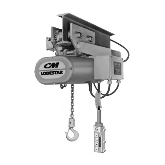
S S e e r r i i e e s s 6 6 3 3 5 5
83875
For more information contact: Sievert Crane and Hoist, (708) 771-1600, parts@sievertelectric.com, www.sievertcrane.com
Operating, Maintenance
& Parts Manual
M M o o t t o o r r D D r r i i v v e e n n T T r r o o l l l l e e y y
C C a a p p a a c c i i t t i i e e s s
1 1 / / 8 8 - - 2 2 a a n n d d 3 3 - - T T o o n n s s
F F
o o l l l l o o w w a a l l l l i i n n s s t t r r u u c c t t i i o o n n s s a a n n d d w w a a r r n n i i n n g g s s f f o o r r
i i n n s s p p e e c c t t i i n n g g , , m m a a i i n n t t a a i i n n i i n n g g a a n n d d o o p p e e r r a a t t i i n n g g t t h h i i s s
t t r r o o l l l l e e y y . .
The use of any hoist and trolley presents some risk of
personal injury or property damage. That risk is great-
ly increased if proper instructions and warnings are
not followed. Before using this trolley, each operator
should become thoroughly familiar with all warnings,
instructions, and recommendations in this manual.
Retain this manual for future reference and use.
Forward this manual to the hoist operator.
Failure to operate the equipment as directed in the
manual may cause injury.
Before using the hoist, fill in the information below.
Refer to the hoist identification plate.
M M o o d d e e l l N N u u m m b b e e r r _ _ _ _ _ _ _ _ _ _ _ _ _ _ _ _ _ _ _ _ _ _ _ _ _ _ _ _ _ _ _ _ _ _ _ _ _ _ _ _ _ _ _ _ _ _ _ _ _ _ _ _ _ _ _ _ _ _ _ _ _ _ _ _ _ _ _ _ _ _ _ _ _ _ _ _ _ _ _ _
S S e e r r i i a a l l N N u u m m b b e e r r _ _ _ _ _ _ _ _ _ _ _ _ _ _ _ _ _ _ _ _ _ _ _ _ _ _ _ _ _ _ _ _ _ _ _ _ _ _ _ _ _ _ _ _ _ _ _ _ _ _ _ _ _ _ _ _ _ _ _ _ _ _ _ _ _ _ _ _ _ _ _ _ _ _ _ _ _ _ _ _
P P u u r r c c h h a a s s e e D D a a t t e e _ _ _ _ _ _ _ _ _ _ _ _ _ _ _ _ _ _ _ _ _ _ _ _ _ _ _ _ _ _ _ _ _ _ _ _ _ _ _ _ _ _ _ _ _ _ _ _ _ _ _ _ _ _ _ _ _ _ _ _ _ _ _ _ _ _ _ _ _ _ _ _ _ _ _ _ _ _ _ _
V V o o l l t t a a g g e e _ _ _ _ _ _ _ _ _ _ _ _ _ _ _ _ _ _ _ _ _ _ _ _ _ _ _ _ _ _ _ _ _ _ _ _ _ _ _ _ _ _ _ _ _ _ _ _ _ _ _ _ _ _ _ _ _ _ _ _ _ _ _ _ _ _ _ _ _ _ _ _ _ _ _ _ _ _ _ _ _ _ _ _ _ _ _ _ _ _ _ _
®
COLUMBUS M c KINNON CORPORATION
INDUSTRIAL PRODUCTS DIVISION
140 JOHN JAMES AUDUBON PARKWAY
AMHERST, NEW YORK 14228-1197
Manual No. 635-J
Advertisement
Table of Contents

Related Manuals for CM 635 Series


Summary of Contents for CM 635 Series
- Page 1 Operating, Maintenance & Parts Manual S S e e r r i i e e s s 6 6 3 3 5 5 M M o o t t o o r r D D r r i i v v e e n n T T r r o o l l l l e e y y C C a a p p a a c c i i t t i i e e s s 1 1 / / 8 8 - - 2 2 a a n n d d 3 3 - - T T o o n n s s o o l l l l o o w w a a l l l l i i n n s s t t r r u u c c t t i i o o n n s s a a n n d d w w a a r r n n i i n n g g s s f f o o r r...
- Page 2 CM HOIST PARTS AND SERVICES ARE AVAILABLE IN THE UNITED STATES AND IN CANADA As a CM Hoist user, you are assured of reliable repair and parts services through a network of Master Parts Depots and Service Centers that are strategically located in the United States and Canada. These facilities have been selected on the basis of their demonstrated ability to handle all parts and repair requirements promptly and efficiently.
-
Page 3: Safety Precautions
SAFETY PRECAUTIONS Each Series 635 Motor Driven Trolley is built in accordance with the specifications contained herein and at the time of manufac- ture complied with our interpretation of applicable sections of the *American Society of Mechanical Engineers Code B30.11 “Monorail Systems and Underhung Cranes,”... - Page 4 NOTES For more information contact: Sievert Crane and Hoist, (708) 771-1600, parts@sievertelectric.com, www.sievertcrane.com...
-
Page 5: Table Of Contents
Specifications ........2 CM Repair/Replacement Policy ....2... -
Page 6: General Information
Trolley develops a performance problem, within 1 (one) year ends of the trolley side frames. of shipment, due to a material or workmanship defect, as ver- ified by CM, repair or replacement of the unit will be made to Trolley to Beam the original purchaser without charge. This... -
Page 7: Washer Spacing Charts
Also, projecting from the side of the gear reducer. This pro- the use of other than CM supplied washers may result in vides a vent for the gear reducer and failure to install trackwheel to beam flange variations and thus Table 2 will the breather may cause the seals to leak. -
Page 8: Hoist To Trolley
Cord (6 Button Control Cord Station Only) Suspension Load Bracket Lug Pin on Trolley Trolley CM Type 4 4 or 6 Button Directional Control Station Control Station Hoist Figure 4. Hoist and Trolley General Arrangement Suspension Lug Electrical Installation... -
Page 9: Hoist Power Cord
Figure 5. Hoist Power Cord Connections: Single-Phase Figure 6. Hoist Power Cord Connections: Three-Phase Hoist Power Cord tab. For cords with the external, chain strain relief, discon- nect the chain from the control station by twisting open the The trolley is supplied with a short hoist power cord connect- link. -
Page 10: Hoist Control Cord
Re-attach the cover to the control station. Energize the OPERATING INSTRUCTIONS power supply system and test the trolley and hoist for proper operation. NOTE: The four-directional control station can only After the trolley and hook travel directions are correct, operate the trolley (according to the operating and safety procedures be used with a hoist that has a reversing contactor. -
Page 11: Maintenance
sure is felt. Hold the plunger firmly in this position and mea- MAINTENANCE sure the air gap between the mating (ground) surfaces of the solenoid (79) and the solenoid plunger (29). To adjust, turn both wear adjustment screws (10) equal amounts clockwise Once a month lubricate trackwheel gear and pinion with until the air gap measures 13/32". -
Page 12: Recommended Spare Parts
8. Re-assemble motor/brake assembly to gear reducer TROUBLESHOOTING using the four nuts and lockwashers. 9. Adjust air gap per above instructions (Adjustment). ELECTRICAL DATA 10. Re-energize power supply and operate trolley a few times to make sure air gap is correct and then replace access To detect open and short circuits in electrical components, covers. -
Page 13: Wiring Diagrams
Figure 9. Typical Wiring Diagrams. Wiring Diagrams shown are representative. Consult diagram attached to contactor or furnished with unit. For more information contact: Sievert Crane and Hoist, (708) 771-1600, parts@sievertelectric.com, www.sievertcrane.com... -
Page 14: Cause And Remedy
TROUBLE SHOOTING ––– Remedy ––– ––– Probable Cause ––– 1. Trolley does not operate in either direction. A. No voltage at trolley A. Main line or branch circuit switch open; branch line fuse blown or circuit breaker tripped. Close, replace or reset. Check for grounded or open connection in supply lines or current collectors. -
Page 15: Replacement Parts
TO AVOID INJURY: For parts orders also specify: Use only CM supplied replacement parts. Parts may look alike, but CM parts are made of specific materials or processed to 1. Quantity desired. achieve specific properties. 2. Key number or part. -
Page 16: Control Stations And Parts List
® 4 DIRECTIONAL CONTROL STATION PARTS LIST Figure 11. Control Station Exploded View. *Refer to parts list on page 15 for information on these parts Key No. Part Name No. Req’d. Part No. 635-21 Warning Tag 81704 635-141 Control Cord Complete Specify Length Required.) 8 Conductors, 16'-3"... -
Page 17: Trolley Components And Parts List
* For Trolleys with standard ranges of adjustment and without trolley guards. 635-12 Trackwheel Stud Nut 988155 988155 For all others, contact CM for side frame part numbers. For more information contact: Sievert Crane and Hoist, (708) 771-1600, parts@sievertelectric.com, www.sievertcrane.com... -
Page 18: Control Box Components And Parts List
Figure 13. Control Box Exploded View. For more information contact: Sievert Crane and Hoist, (708) 771-1600, parts@sievertelectric.com, www.sievertcrane.com... - Page 19 635-30 C.M. Nameplate 935899 936828 Three-Phase 982683 (1/8 – 2-Ton) (3-Ton) 635-72* Gasket Cement 986913 635-31 Wiring Diagram Contact CM 635-76 Hoist Control Cord Connector 89926 635-32 Current Label 635-77* Hoist Control Cord Connector “O” Ring 983967 115-1-60 935884 635-78...
-
Page 20: Motor And Hub City Type
Figure 14. Motor and Hub City Type Gear Reducer Exploded View. Key No. Part Name No. Req’d. Part No. Key No. Part Name No. Req’d. Part No. 635-329 Shaft, Output Contact CM 635-89 Gear Reducer Mtg. Screw 927764 635-330 Worm, Integral Contact CM 635-90 Gear Reducer Screw L.W. 982226 635-331... -
Page 21: Motor And Gear Reducer Components And Parts List
Part No. Key No. Part Name No. Req’d. Part No. 635-89 Gear Reducer Mtg. Screw 927764 635-406 Retaining Ring Contact CM 635-407 Retaining Ring Contact CM 635-90 Gear Reducer Screw L.W. 922226 635-408 High Speed Cap Closed Contact CM 635-91... -
Page 22: Motor Brake
Key No. Part Name No. Req’d. Part No. 635-206 Brake Cord 51074 635-278 Torque Adjusting Screw Contact CM 635-260 Coupler Brake Shaft Kit Contact CM 635-279 Wear Adjusting Screw Contact CM (Includes Shaft, Bearing, Snap Ring, Retainer Ring and Key) - Page 23 NOTES For more information contact: Sievert Crane and Hoist, (708) 771-1600, parts@sievertelectric.com, www.sievertcrane.com...
- Page 24 For the location of the nearest CM Master Parts Depot, see the list located on the inside front cover. LIMITATION OF WARRANTIES, REMEDIES AND DAMAGES...
Need help?
Do you have a question about the 635 Series and is the answer not in the manual?
Questions and answers