Table of Contents
Advertisement
Quick Links
O P E R AT I N G ,
M A I N T E N A N C E &
PA R T S M A N U A L
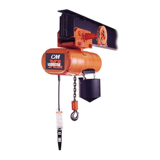
E L E C T R I C
C H A I N H O I S T
®
Before installing hoist, fill in the
information below. Refer to the
hoist identification plate.
Model no. __________________
Serial no. ___________________
Purchase date ______________
Voltage _____________________
Rated capacity ______________
52756
S
O
L
U
Rated capacities 2 through 6 tons/
2000 through 6000 kg
Follow all instructions and warnings for
inspecting, maintaining and operating this hoist.
The use of any hoist presents some risk of personal
injury or property damage. That risk is greatly
increased if proper instructions and warnings are not
followed. Before using this hoist, each operator
should become thoroughly familiar with all warnings,
instructions and recommendations in this manual.
Retain this manual for future reference and use.
Forward this manual to operator.
Failure to operate equipment as directed
in manual may cause injury.
T
I
O
N
®
Manual No. 652-B
S
Advertisement
Table of Contents

Related Manuals for CM LODESTAR XL


Summary of Contents for CM LODESTAR XL
- Page 1 O P E R AT I N G , M A I N T E N A N C E & PA R T S M A N U A L E L E C T R I C C H A I N H O I S T ®...
- Page 2 CM HOIST PARTS AND SERVICES ARE AVAILABLE IN THE UNITED STATES AND IN CANADA As a CM Hoist user, you are assured of reliable repair and parts services through a network of Master Parts Depots and Service Centers that are strategically located in the United States and Canada. These facilities have been selected on the basis of their demonstrated ability to handle all parts and repair requirements promptly and efficiently.
-
Page 3: Safety Precautions
SAFETY PRECAUTIONS Each Lodestar XL Electric Hoist is built in accordance with the specifications contained herein and at the time of manufacture complied with our interpretation of applicable sections of the *American Society of Mechanical Engineers Standard B30.16 “Overhead Hoists,” the National Electrical Code (ANSI/NFPA 70) and the Occupational Safety and Health Act. Since OHSA states the National Electrical Code applies to all electric hoists, installers are required to provide current overload protection and grounding on the branch circuit section in keeping with the code. -
Page 5: Table Of Contents
LUBRICATION CM REPAIR/REPLACEMENT POLICY ..3 HOIST ......14 ACCESSORIES . -
Page 6: General Information
• Weatherproof, CM snap action 2 or 4 direction control station. The Lodestar XL Electric Chain Hoist is a highly versatile • Shielded, lifetime lubricated ball bearings at all material handling device that can be used to lift loads that rotating points. -
Page 7: Cm Repair/Replacement Policy
Hook suspensions are available for suspending the hoist moved by the means of a hand chain. The hand chain from a trolley with a single load bar (such as CM’s Series rotates a pinion that drives gears attached to trolley wheels 639 trolleys) or for suspending the hoist from a fixed struc- and moves trolley along the beam. -
Page 8: Unpacking
8. CHAIN CONTAINER LATCHLOK® HOOKS CM’s Latchlok hooks are available to replace the standard upper or lower latch type hooks. The unique design of the Latchlok hook assures that it will stay locked until the operator releases it by depressing the release button. - Page 9 2 TON UNIT MOUNTING THE COUNTERWEIGHT Attach the “Lodestar XL” label, from the kit, to counter- weight in the recess provided for same. NOTE: INSTALL BREATHER IN MAIN HOUSING AFTER 2. 2 Ton Single Reeved Units. As shipped from the fac- HOOK SUSPENSION IS ASSEMBLED TO HOIST.
-
Page 10: Lug Suspensions
On tighten the keeper plate screw while making sure the loose units shipped from CM, these trolleys are mounted on the pin engages the slot in keeper plate. hoists. -
Page 11: Installing Trolley Suspended Hoist On Beam
Texaco Novatex #2 or equivalent heavy cup grease. If CM’s washer spacing recommendations are not fol- lowed, trolley may fall from beam. On open end beams, remove rail stops, lift hoist/trolley into... -
Page 12: Installing Breather
When determining the size of branch circuit com- TEMS. HOWEVER, WITH NO MODIFICATION, THE ponents and conductors,special consideration LODESTAR XL HOIST WILL OPERATE ON A RANGE OF should be given to the starting current-amps VOLTAGES AS INDICATED BELOW: (approximately three times that shown on the... -
Page 13: All Hoists
1. Remove the motor cover (652-182). On units with Lockout/Tagout procedures when working (connecting or hook suspension, it will be necessary to remove the coun- disconnecting) with the hoist electrical connections. terweight (652-219) before removing motor cover. WARNING 2. Shift all eight wires from row of terminals marked “460”... -
Page 14: Checking For Adequate Voltage
*Refer to limitations on Page ii concerning dumbwaiter Do not allow the hook block to contact the bottom of hoist or the loose end chain to become taut. applications. Also, if a Lodestar XL Hoist with a Protector is used at... -
Page 15: All Hoists
It is not necessary to load. When in doubt, use the next larger capacity of CM operate in the SLOW speed position as the hoist will pick Lodestar XL Hoist. -
Page 16: Inspections
DETAILED INSPECTION, WHICH, IN TURN, MAY REQUIRE THE USE OF NONDESTRUCTIVE TYPE TEST- Brake Cover ING. (652-181) Lodestar XL HOOK INSPECTION Hoist with Motor Hooks damaged from chemicals, deformations or cracks, or Driven Trolley that have more than a 10° twist from the hook’s unbent plane, excessive opening or seat wear must be replaced. - Page 17 Table 3. Minimum Frequent Inspections TYPE OF SERVICE ITEM Severe Normal Heavy Brake for evidence of slippage. Control functions for proper operation. Hooks for damage, cracks, twists, excessive throat opening. latch engagement and latch operation–see page 12. Load chain for adequate lubrication, as well as for signs of wear, damaged links or foreign matter–see page 14.
-
Page 18: Load Chain
Used motor oils contain unknown carcinogenic materials. without service. The device has been calibrated at the fac- tory for a specific capacity/gear ratio of Lodestar XL Hoist. TO AVOID HEALTH PROBLEMS: It is not adjustable and it is not interchangeable with other Never use used motor oils as a chain lubricant. -
Page 19: Adjustments
Geared Trolley. Once a month lubricate trackwheel gears with Texaco Novatex No. 2 or an equivalent heavy cup grease or graphite grease. Every six months lubricate handwheel shaft bearings in 3- in-1 machine oil. Motor Driven Trolley. Once a month lubricate trackwheel gears with Texaco Novatex No. -
Page 20: Trolley Brake
46 (14) 0.42 (10.8) 6 (6000) 6 (1.8) 42 (13) 0.37 (9.3) To insure continued service of the Lodestar XL Hoist, the following is a list of parts that are recommended 6 (6000) 8 (2.4) 46 (14) 0.42 (10.8) to be kept on hand at all times to replace parts that have worn or failed. -
Page 21: Trouble Shooting
TROUBLE SHOOTING TROUBLE PROBABLE CAUSE CHECK AND REMEDY ALL HOISTS Hook does not A) No voltage at hoist—main line or A) Close switch, replace fuse or reset branch circuit switch open; branch breaker. respond to the control line fuse blown or circuit breaker station. - Page 22 TROUBLE PROBABLE CAUSE CHECK AND REMEDY A) Check connections with the wiring A) Wiring connections reversed at either 2. Hook moves in the the control station or terminal board. diagram. wrong direction. B) Phase reversal. B) Refer to installation instructions on page 9 (all hoists).
- Page 23 TROUBLE PROBABLE CAUSE CHECK AND REMEDY A) See Item 1H. A) Excessive Load 8. Motor overheats. B) Low Voltage B) Check for low voltage condition as described on page 10. C) Extreme external heating. C) Above an ambient temperature of 104°F.
-
Page 24: Two Speed Hoists
TROUBLE PROBABLE CAUSE CHECK AND REMEDY TWO SPEED HOISTS A) Open or shorted motor winding, 11. Hoist will not operate A) Open Circuit. loose or broken wire in circuit, at slow speed in speed selecting contactor stuck either direction. in opposite speed mode. Replace motor, repair wire and/or replace speed selecting contactor. -
Page 25: Motor Driven Trolley
TROUBLE PROBABLE CAUSE CHECK AND REMEDY MOTOR DRIVEN TROLLEY 18) Trolley does not A) No voltage at motor A) Open circuit, grounded or faulty operate in either connection in hoist wiring. direction B) Phase failure B) See Item 1B. C) Open control circuit C) See Item 1D. -
Page 26: Electrical Data
ELECTRICAL DATA TO DETECT OPEN AND SHORT CIR- CUITS IN ELECTRICAL COMPONENTS Open circuits in the coils of electrical components may be substantially below normal. The current method is recom- detected by isolating the coil and checking for continuity mended for coils with very low D.C. resistance. with an ohmmeter or with the unit in series with a light or bell circuit. - Page 27 HOIST MOTORS (652-162) CURRENT (AMPS) *D.C. RESISTANCE (OHMS)-LEADS VOLTS-PHASE H.P. 11-12 STARTING FULL LOAD -HERTZ (KW) 11-13 12-13 230/460-3-60 3.5 (2.7) 18.4/6.4 11.5/5.8 – – 220/380-3-50 3.5 (2.7) 13.6/6.4 11.9/5.9 – – 13.6/6.4 11.9/5.8 220/415-3-50 3.5 (2.7) – – 230-3-60 1.2/3.5 49.2/40.8 12.3/10.2...
- Page 28 TYPICAL WIRING DIAGRAMS Wiring diagrams shown are representative. Consult wiring diagram in hoist or furnished with unit.
-
Page 30: Disassembly
Seals should be inspected for nicks or dam- USE ONLY CM STAR ( ) GRADE LOAD CHAIN AND age that could cause oil leaks. Damaged seals should be CM REPLACEMENT PARTS. -
Page 31: Reeving Load Chain
when the entire hoist is disassembled for repair and /or engage the relief machined in the bottom of the inspection. liftwheel pockets. METHOD 1 Disconnect the hoist from the power supply sys- If the chain is not properly placed on the tem. -
Page 32: And 6 Ton Triple Reeved Units
HOOK SUSPENSION SHOWN LUG SUSPENSION SIMILAR HOOK SUSPENSION SHOWN LUG SUSPENSION SIMILAR CUTTING CHAINS CM Hoistaloy load chain is hardened and it is difficult to cut. Retrace the chain and make sure there are no The following methods are recommended when cutting a twists. -
Page 33: Testing
WARNING TESTING Using “commercial” or other manufacturer’s parts to repair the CM Lodestar XL Hoists may cause load loss. Before using, all altered, repaired or used hoists that have not been operated for the previous 12 months shall be test- TO AVOID INJURY: ed by the user for proper operation. -
Page 34: Exploded Views And Parts Lists
Lodestar XL Electric Chain Hoist Parts List KEY NO. NO. REQ’D PART NAME PART NUMBER KEY NO. NO. REQ’D PART NAME PART NUMBER 652-100 BRAKE HUB SNAP RING 35764 652-138 TROLLEY REVERSING CONTACTOR 652-101 2ND GEAR SNAP RING 36763 WITH :... - Page 35 KEY NO. NO. REQ’D PART NAME PART NUMBER KEY NO. NO. REQ’D PART NAME PART NUMBER 652-165 CONTACTOR MOUNTING PLATE SCREW 983747 652-191 COIL RETAINER STRAP 35704 652-166 CONVERSION T.B. BRACKET 52705 652-192 BRAKE BASE PLATE 52607 652-167 BRACKET ATTACHING SCREW 982683 652-193 BRAKE FIELD PLATE...
- Page 36 When ordering lubricants, specify the type of lubricant, part number and packaged quantity required. Touch-up Paints for Lodestar XL Electric Chain Hoists order: (1) case (12-12 oz. Aerosol Cans) of Orange Touch-up paint Part Number 84190. Touch-up paint is only available in case quantities.
- Page 37 652-240 652-235 652-241 652-242 652-239 652-184 652-236 652-138 652-181 652-245 652-22 652-238 652-234 652-21 652-237 652-197 652-226 652-193 652-130 652-194 652-196 652-225 652-131 652-195 652-186 652-192 652-131 652-191 652-154 652-231 652-161 652-120 652-244 652-155 652-230 652-228 652-134 652-147 652-141 652-146 652-104 652-229 652-141...
- Page 38 652-198 652-145 652-219 652-140 652-245 652-144 652-157 652-223 652-258 652-110 652-257 652-186 652-256 652-189 652-255 652-113 652-107 652-158 652-127 652-151 652-103 652-162 652-128 652-150 652-114 652-211 652-178 652-214 652-140 652-180 Lodestar XL Electric Chain Hoist 652-212 652-214 Exploded View 652-180...
- Page 39 670-350 652-303 652-186 652-182 652-303 652-300...
- Page 40 670-462 670-463 670-319 652-302 652-301 670-337 PLAIN, GEARED AND MOTOR 670-341 DRIVEN TROLLEYS - 670-420 PLAIN, GEARED AND MOTOR DRIVEN TROLLEYS - EXPLODED VIEW 652-186...
- Page 41 652-302 SUSPENSION ADAPTER SCREW / DEAD END BOLT 987208 80430 5.00” TO 6.25” FLANGE (127.0 to 158.7 mm) — 70683 652-303 “CM” LABEL 25779 6.26” TO 7.63” FLANGE (159.0 to 193.8 mm) — 57631 670-304 SUSPENSION BOLT FOR : 670-320 2 REQ’D.
- Page 42 KEY NO. NO. REQ’D PART NAME PART NUMBER KEY NO. NO. REQ’D PART NAME PART NUMBER 2 TON 3-6 TON 2 TON 3-6 TON 670-346 INTERMEDIATE GEAR FOR : 670-374 TERMINAL BOX SCREW L.W. 982226 35 AND 65 FPM TROLLEYS (10.7 and 19.8 MPM) 58453 58453 670-375...
- Page 43 Control Station, Single Speed, Exploded View 28630 Control Station, Two Speed, Exploded View...
- Page 44 Control station switch kit 71602 Consisting of: 6-Switch 2-Interlocks 635-156 Control station complete: *CM 4 directional (1 or 2 speed 70620 635-156 hoist with 1 speed trolley) 6 button type SPB (on-off, 58209 1 speed hoist, 1 speed trolley) (For other control stations, –...
- Page 45 NOTES:...
- Page 46 For the location of the nearest CM Master Parts Depot, see the list located on the inside front cover. LIMITATION OF WARRANTIES, REMEDIES AND DAMAGES THE WARRANTY STATED BELOW IS GIVEN IN PLACE OF ALL instructions and recommendations;...
Need help?
Do you have a question about the LODESTAR XL and is the answer not in the manual?
Questions and answers