Table of Contents
Advertisement
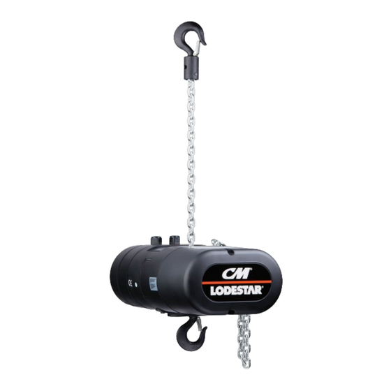
INSTALLATION, OPERATING
& MAINTENANCE MANUAL
ELECTRIC CHAIN HOIST
ADJUSTABLE CLUTCH MODEL
ADJUSTABLE CLUTCH UNITS IDENTIFIED WITH PRODUCT CODE PREFIX "A"
Before installing hoist, fill in the information below.
Model Number
Serial No.
Purchase Date
Voltage
Rated Load
RATED LOADS 1/4 TO 2 TONNES
250 KG TO 2000 KG
WARNING
Follow all instructions and warning for inspecting,
maintaining and operating this hoist.
The use of any hoist presents some risk of personal injury
or property damage. That risk is greatly increased if proper
instructions and warnings are not followed. Before using
this hoist, each operator should become thoroughly familiar
with all warnings, instructions and recommendations in this
manual. Retain this manual for future reference and use.
Forward this manual to operator. Failure to operate equipment
as directed in manual may cause injury.
10001921 REV AC July 2019
Advertisement
Table of Contents
Troubleshooting

Related Manuals for CM Lodestar Series


Summary of Contents for CM Lodestar Series
- Page 1 INSTALLATION, OPERATING & MAINTENANCE MANUAL ELECTRIC CHAIN HOIST ADJUSTABLE CLUTCH MODEL ADJUSTABLE CLUTCH UNITS IDENTIFIED WITH PRODUCT CODE PREFIX "A" Before installing hoist, fill in the information below. Model Number Serial No. Purchase Date Voltage Rated Load RATED LOADS 1/4 TO 2 TONNES 250 KG TO 2000 KG WARNING Follow all instructions and warning for inspecting,...
-
Page 2: General Information Online Resources
NAME OF THE NEAREST PARTS OR SERVICE CENTER, VISIT OUR WEB SITE WWW.CMWORKS.COM OR CALL OUR CUSTOMER SERVICE DEPARTMENT AT 800-888-0985. AN ELECTRONIC COPY OF THIS MANUAL AND THE CM HOIST PARTS AND SERVICES LIST IS AVAILABLE AT: http://www.cm-et.com/products.aspx?id=23221 WARNING Follow all instructions and warning for inspecting, maintaining and operating this hoist. -
Page 3: Safety Precautions
The safety laws for elevators, lifting of people and for dumbwaiters specify construction details that are not incorporated in CM hoists. For such applications, refer to the requirements of applicable state and local codes, and the American National Safety Code for elevators, dumbwaiters, escalators and moving walks (ASME A17.1). -
Page 4: Table Of Contents
FOREWORD This manual contains important information to help you properly install, operate and maintain your hoist for maximum performance, economy and safety. Please study its contents thoroughly before putting your hoist into operation. By practicing correct operating procedures and by carrying out the recommended preventive maintenance suggestions, you will experience long, dependable and safe service. -
Page 5: Specifications
2.16 ACCESSORIES LATCHLOK®HOOKS HOOK SUSPENSIONS CM’s Latchlok hooks (see Figure 2) are available Swivel and rigid type hook suspensions to replace the standard upper and lower hooks (see Figure 1) are available for all Lodestar used on the Lodestar Electric Hoists. -
Page 6: Unpacking Information
INSTALLATION UNPACKING INFORMATION Using other than CM supplied high strength suspension screws to When received, the hoist should be carefully inspected for damage attach the suspension adapter to the hoist may cause the screws which may have occurred during shipment or handling. Check to break and allow the hoist and load to fall. -
Page 7: Attaching Load Chain
CUTTING CHAIN CHECKING FOR TWIST IN LOAD CHAIN MODELS R, RR CM®Load chain is hardened and it is difficult to cut. The following The best way to check for this condition is to run the lower hook, methods are recommended when cutting a length of new chain from without a load, up to within about 2 feet (.61 Meters) of hoist. -
Page 8: External Chain Plate
or 230-3-60) simply remove the 9 and 12 pin plugs from the "Red" receptacles and insert same into the "White" receptacles located on the voltage change board. Be sure to make a notation of the new hoist voltage on the tag attached to the power cord. Cutting Chain Can Produce Flying Particles. -
Page 9: Checking Limit Switch Operation
£, up direction with full load) must be as indicated in the table below. Remember, operation with low voltage can void the CM repair/ replacement policy. When in doubt about any of the electrical Table 2. Voltage Requirements requirements, consult a qualified electrician. -
Page 10: Operating Instructions General
When in doubt, use the next larger capacity CM Lodestar Hoist. OPERATING INSTRUCTIONS Warn personnel of your intention to lift a load in the area. -
Page 11: Inspection
INSPECTION When running chain “out”, the same principal should be adopted but this time with the “dead” end side of the hoist facing up. Again, this To maintain continuous and satisfactory operation, a regular will prevent twists causing chain jam. inspection procedure must be initiated to replace worn or damaged parts before they become unsafe. -
Page 12: Inspection Schedule
TABLE 4. INSPECTION TABLE Service Classifications Item Out of Severe Normal Stand By Rental Service Hoist braking system for proper operation Hooks and attachment hardware for correct assembly, damage, cracks, twists, excessive throat openings, latch engagement, and latch operation Load chain for adequate lubrication, signs of wear, damaged links, corrosion, or foreign matter Load chain for proper reeving and twists Limit switches for function, if equipped... -
Page 13: Replacement Criteria
HOOK REPLACEMENT CRITERIA Slack the portion of the chain that normally passes over the a. Missing or illegible rated load identification or illegible lift-wheel (sprocket) or idler sprocket on multi-reeved hoist. hook manufacturers' identification or secondary Based on ASME B30.10, hooks shall be removed from service Examine the chain links for wear (see Figure 13). -
Page 14: Removal And Installation
Run enough chain through to attach loose end link to hoist frame. USE ONLY CM EN (formerly DIN) OR STAR () GRADE LOAD CHAIN AND CM REPLACEMENT PARTS. USE OF OTHER CHAIN CAUTION: For double reeved models, be sure to disconnect... -
Page 15: Ordering Instructions
Using “Commercial” or other manufacturer’s parts to repair the CM Lodestar Hoists may cause load loss. TO AVOID INJURY: Use only CM supplied replacement parts. Parts may look alike but CM parts are made of specific materials or processed to achieve specific properties... -
Page 16: Hoist Lubrication
If desired, these lubricants Loosen the 2 screws or spring back the rotatable guide to may be purchased from CM. Refer to spare parts section for disengage the travel nut. information on ordering the lubricants. -
Page 17: Limit Switches, Models B-F
Table 8. Limit Switch - Dimensions SETTING UPPER LIMIT SWITCH A (minimum After completing steps 1 thru 4 Hook Travel, per distance between B (minimum length Refer to Table 8 -The "A" Dimensions given are the minimum Notch top of hook block Model of loose end chain distance that should be set between the top hook block and the... -
Page 18: Troubleshooting
10. Securely reposition the guide plate in the slot 11. Reconnect hoist to power supply and check the stopping point of hook by first lowering the hook about 2 feet (61 cm), then TESTING OF MECHANICAL raise the hook by jogging cautiously until the upper limit switch stops upward motion. -
Page 19: Troubleshooting
TABLE 9. TROUBLESHOOTING CHART SYMPTOM PROBABLE CAUSE CORRECTIVE ACTION 1.) Hook does not respond to the A.) No voltage at hoist-main line or branch A.) Close switch, replace fuse or reset breaker. control station or control device circuit switch open; branch line fuse blown or circuit breaker tripped. -
Page 20: Electrical Data
TABLE 9. TROUBLESHOOTING CHART SYMPTOM PROBABLE CAUSE CORRECTIVE ACTION 6.) Hook does not stop promptly. A.) Brake slipping. A.) Check brake adjustment as described on page 15. B.) Excessive load. B.) See item 1H. 7.) Hoist operates sluggishly. A.) Excessive load. A.) See item 1H. -
Page 21: Torque Specifications
ELECTRICAL DATA TO DETECT OPEN AND SHORT CIRCUITS IN Table 10c. Electric Brake Data ELECTRICAL COMPONENTS DC Brake Coil Nominal Current *D.C. Resistance Models Voltage (Amps) (Ohms) Open circuits in the coils of electrical components may be detected by isolating the coil and checking for continuity with an ohmmeter 0.243 424.4 or with the unit in series with a light or bell circuit. - Page 22 TORQUE SPECIFICATIONS Table 11c. Torque Specification: Models J-RR *Recommended Fastener Table 11a. Torque Specification: All Models Seating Torque Fastener Tool Required Description ft-lbf *Recommended Fastener Seating Torque Fastener Tool Required Motor Housing / Gear Description 5/16"-18 Socket Head Housing / Back Frame 1/4"...
- Page 23 NOTES 10001921 REV AC July 2019...
- Page 24 10001921 REV AC July 2019 © 2018 Columbus McKinnon Corporation. All Rights Reserved.
Need help?
Do you have a question about the Lodestar Series and is the answer not in the manual?
Questions and answers