
Related Manuals for horsch Tiger AS Series


Summary of Contents for horsch Tiger AS Series
- Page 1 Operating Instructions Tiger AS LT MT XL Art.: 80580203 en Read carefully prior to starting up! Issue: 09/2014 Keep operating instructions in a safe place!
- Page 2 EC Declaration of Conformity exchangeable equipment (RL 2006/42/EC) The manufacturer HORSCH Maschinen GmbH Sitzenhof 1 D-92421 Schwandorf hereby declares, that the product, Designation of machine: Cultivation tool Machine type: from serial no.: 34731531 Tiger 3 AS from serial no.: 34741612 Tiger 4 AS / rigid from serial no.: 34751375...
- Page 3 EC Declaration of Conformity exchangeable equipment (RL 2006/42/EC) The manufacturer HORSCH Maschinen GmbH Sitzenhof 1 D-92421 Schwandorf hereby declares, that the product, Designation of machine: Cultivation tool Machine type: from serial no.: 34631478 Tiger 3 MT from serial no.: 34641912 Tiger 4 MT / rigid from serial no.: 34651399...
- Page 4 EC Declaration of Conformity exchangeable equipment (RL 2006/42/EC) The manufacturer HORSCH Maschinen GmbH Sitzenhof 1 D-92421 Schwandorf hereby declares, that the product, Designation of machine: Cultivation tool Machine type: from serial no.: 34701317 Tiger 5 LT from serial no.: 34711526 Tiger 6 LT from serial no.: 34721381...
- Page 5 EC Declaration of Conformity exchangeable equipment (RL 2006/42/EC) The manufacturer HORSCH Maschinen GmbH Sitzenhof 1 D-92421 Schwandorf hereby declares, that the product, Designation of machine: Cultivation tool Machine type: from serial no.: 34811310 Tiger 6 XL from serial no.: 34821283...
- Page 7 I hereby confirm receipt of the operating instructions for the above mentioned machine. I have been instructed by a HORSCH service technician or authorised dealer in the operation and functions of the machine, as well as in the safety requirements.
- Page 9 ..............Road: ..............Town/City: ..............Tel.: ..............Customer No.: Retailer: ..............Address of HORSCH: HORSCH Maschinen GmbH 92421 Schwandorf, Sitzenhof 1 92401 Schwandorf, Postbox 1038 Tel.: +49 (0) 9431 / 7143-0 Fax: +49 (0) 9431 / 7143-9200 E-mail: info@horsch.com Customer No.: HORSCH: ..............
-
Page 10: Table Of Contents
Inhaltsverzeichnis Introduction ...........4 TerraGrip tool carrier........39 Foreword ............4 Maintenance ..........39 Notes on representation .........4 Coulter ............39 Goliath tines..........40 Service ............5 Maintenance ..........40 Warranty claim processing ......5 Hydraulic tine protection .......41 Consequential damage........5 Maintenance ..........41 Packer ............41 Safety and responsibility ......6 Maintenance ..........42 Intended use ...........6 Disc levelling..........42... - Page 11 Optional equipment ........51 TopRing Packer ..........51 Operation ...........51 Maintenance ..........51 Bout marker ..........52 Operation ...........52 Maintenance ..........52 Rear pulling tool..........53 Maintenance ..........53 SteelDisc Packer ..........53 Maintenance ..........53 Fertiliser distribution ........53 Maintenance ..........54 Adjusting the fertiliser placement ....54 Optional equipment ........55 Brake system ..........55 Pneumatic brake ........55 Hydraulic brake ..........56...
-
Page 12: Introduction
DANGER the safety notices! Highlights a danger that will lead to death or HORSCH will not assume liability for any dam- severe injury, if it is not avoided. age or malfunctions resulting from failure to comply with the operating instructions. -
Page 13: Service
Service Consequential damage The machine has been manufactured by The company HORSCH would be pleased, if HORSCH with greatest care. However, despite your machine and our services would meet your the intended use deviations in placement quan- expectations. tity up to total failure may be caused by e.g.:... -
Page 14: Safety And Responsibility
Safety and Spare parts Genuine spare parts and accessories from responsibility HORSCH have been specially designed for this machine. Spare parts and accessories which are not de- The following warnings and safety instructions ap- livered by us, have not been tested or approved ply to all sections in these operating instructions. -
Page 15: Qualification Of Personnel
The person has understood the operating ¾ service personnel from HORSCH. This refers to instructions and is able to implement the in- the following activities: formation given in the operating instructions Loading and transport accordingly. -
Page 16: Personal Protective Outfit
Do not exceed the permissible axle loads, tyre after receiving instructions by employees of the carrying capacities and total weights, in order to authorized dealer or a HORSCH employee. ensure sufficient steering and braking capabili- The machine registration form must be com- ties. - Page 17 Damage to the machine Hydraulic system Damage to the machine can impair the op- The hydraulic system is under high pressure. erational safety of the machine and cause ac- Hydraulic oil escaping under pressure can pen- cidents. This can lead to severe or even fatal etrate the skin and cause serious injuries.
- Page 18 If the technical limiting values of the machine workshop or by an operator, who has been are not complied with, the machine may get specially trained by HORSCH. damaged. This can lead to accidents with severe or even fatal physical injuries.
-
Page 19: Fertiliser And Dressed Seed
Fertiliser and dressed Use in the field seed DANGER Inappropriate handling of fertiliser and dressed No passengers are allowed to ride on the seed can cause poisoning and death. machine! Follow the information given in the safety ¾ data sheet of the manufacturer. If necessary Check the area around the machine (for chil- ¾... -
Page 20: Retrofits
Structural changes and extensions must only ¾ maintenance plan, see chapter “Care and be made in an authorized workshop or by an maintenance”. operator who has been trained by HORSCH. Only perform the work described in these ¾ Comply with country specific instructions fr ¾... -
Page 21: Danger Zone
Danger zone Failing to pay attention to the danger zone can The area marked red indicates the danger zone of the machine: result in severe or even fatal physical injuries. Do not stand under lifted loads. Lower such ¾ loads to the ground first. Instruct persons to leave the danger zone ¾... -
Page 22: Safety Stickers
Safety stickers Safety stickers on the machine warn of en- Clean soiled safety stickers. ¾ dangerments at dangerous points and are an Damaged or illegible safety stickers must be ¾ important part of the safety equipment of the replaced immediately. machine. - Page 23 It is only permitted to remain in the The pressure accumulator is danger zone if the safety support charged with gas or oil pressure. is in place. Dismantle and repair only in strict compliance with the instructions in the technical manual. 00380252 00380953 Position of safety stickers...
- Page 24 00380134 00380135 00380896 00380953 00380299 00380054 00380055 00380133 00380294 00380134 00380135 Tiger 8 LT 00380299 00380896 00380953 00380134 00380135 00380252 00380054 00380055 00380133 00380294 00380134 00380135 Tiger 8 MT...
- Page 25 00380134 00380135 00380896 00380299 00380134 00380135 00380953 00380054 00380055 00380133 00380294 Tiger 8 XL...
-
Page 26: Commissioning
Commissioning Installation Instruction of the operator and initial installation Higher danger of accidents during commission- of the machine will be carried out by our service ing. Please pay attention to the notes in the engineers or distributors. corresponding chapters. Any preceding use of the machine is Delivery prohibited! The machine with implements is normally de-... -
Page 27: Technical Data
Technical data Tiger 3 AS 4 AS rigid 4 AS Working width (m) 3.00 4.00 4.00 Transport width (m) 3.00 4.05 3.00 Transport height (m) 1.90 1.90 2.90 Length with tyre packer 7.50-16 (m) 7.95 7.95 7.95 Length with tyre packer 210/95-24 (m) 8.30 8.30 Weight (kg)*... - Page 28 Tiger 5 AS 6 AS 8 AS Working width (m) 4.80 6.00 7.50 Transport width (m) 3.00 3.00 3.00 Transport height (m) 3.30 3.80 4.00/4.15 (with levelling discs 2-row) Length with tyre packer 7.50-16 (m) 7.95 7.95 7.95 Length with tyre packer 210/95-24 (m) 8.30 8.30 8.30...
- Page 29 Tiger 5 LT 6 LT 8 LT Working width (m) 4.80 6.00 7.50 Transport width (m) 3.00 3.00 3.00 Transport height (m) 3.30 3.70 4.00/4.15 (with levelling discs 2-row) Length with tyre packer 7.50-16 (m) 7.05 7.05 7.05 Length with tyre packer 210/95-24 (m) 7.40 7.40 7.40...
-
Page 30: Type Plate
(bar) 210 Design related top speed 40 km/h** / Data in type approval Type plate HORSCH Maschinen GmbH Sitzenhof 1, D-92421 Schwandorf The type plate with the CE-mark is located Tel. +49 (0) 9431 / 7143-0 on the frame of the machine. - Page 31 Tiger 5 MT 6 MT 8 MT Working width (m) 4.80 6.00 7.50 Transport width (m) 3.00 3.00 3.00 Transport height (m) 3.20 3.60 4.00/4.15 (with levelling discs 2-row) Length with tyre packer 7.50-16 (m) 8.55 8.55 8.55 Length with tyre packer 210/95-24 (m) 8.90 8.90 8.90...
- Page 32 Tiger 6 XL 8 XL Working width (m) 6.00 7.50 Transport width (m) 3.00 3.00 Transport height (m) 3.60 4.00 Length with tyre packer 7.50-16 (m) 9.30 9.30 Length with tyre packer 210/95-24 (m) 9.65 9.65 Weight (kg)* 6,990 8,480 Number of tines Tine spacing in row (cm) Groove spacing (cm)
- Page 33 Tiger 8 AS (Machine with basic equipment and swinging drawbar hitching) Tiger 8 LT (Machine with basic equipment and swinging drawbar hitching)
- Page 34 Tiger 8 MT (Machine with basic equipment and swinging drawbar hitching) Tiger 8 XL (Machine with basic equipment and swinging drawbar hitching)
-
Page 35: Calculating The Ballasting
Calculating the ballasting Required data: The permissible total weight, the permissible axle loads and the load bearing capacity of the tyres must not be exceeded when mounting or hitching up implements. The front axle of the tractor must always be loaded with at least 20 % of the curb weight of the tractor. - Page 36 1. Calculation of minimum front ballasting 4. Calculation of the actual total weight with rear implement: • (c + d) - T • b + 0.2 • T • b Enter the result of the calculated total weight and a + b V min the permissible total weight from the operating instructions of the tractor into the table.
-
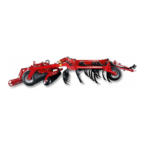
Page 37: Design
Design Overview Tiger 6 AS with DuoDrill The HORSCH Tiger AS are characterized by 1 Hitching with connections hydraulic/electric their robust design and the TerraGrip tool carrier 2 Support for deep cultivation down to 35 cm. 3 Sensing wheels 4 Tine field, 4-beam... - Page 38 Tiger 6 MT The HORSCH Tiger MT are characterized by 1 Hitching with connections hydraulic/electric their robust design and the TerraGrip tool carrier 2 Support for deep soil cultivation. 3 DiscSystem, two-row With their combination of tines with large coulter...
- Page 39 Tiger 6 LT The HORSCH Tiger LT are most suitable for 1 Hitching with connections hydraulic/electric deep soil cultivation on light to medium soils. 2 Support 3 Sensing wheels With the three-beam arrangement of tines and 4 Tine field, three-beam...
- Page 40 Tiger 6 XL The HORSCH Tiger XL are most suitable for 1 Hitching with connections hydraulic/electric stubble processing on all types of soil. 2 Support 3 Sensing wheels The six-beam arrangement with a tine spacing 4 Tine field, six-beam of 16 cm ensures uniform cultivation and mixing 5 Levelling discs of soil with harvest residues.
-
Page 41: Hydraulic System
Hydraulic system Tiger 3 & 4 AS rigid WARNING Accidental hydraulic movements (e.g. caused by passengers or children) can lead to severe accidents and injuries! Secure or lock the control units on the tractor. Instruct persons to leave the swivelling range of foldable machine parts. -
Page 42: Tiger 4 - 8 (Two-Point Hitching)
Tiger 4 - 8 (two-point hitching) Z2 Z3 Z1 Hydraulics Tiger 4 - 8 with two-point hitching 1 Control unit 11 Shut-off valve, disc levelling 2 Hydraulic coupling 12 Hydraulic cylinder disc feeder 13 Hydraulic valve packer 3 Hydraulic lock valve 4 Hydraulic cylinder for wings 14 Pressure gauge Zeichnungsnummer... -
Page 43: Tiger 5 - 8 (Swinging Drawbar Hitching)
Tiger 5 - 8 (swinging drawbar hitching) Z2 Z3 Z1 Hydraulics Tiger 4 - 8 with adjustable drawbar hitching 1 Control unit 11 Lock valve 2 Hydraulic coupling 12 Hydraulic cylinder disc feeder 13 Hydraulic valve packer 3 Hydraulic lock valve 4 Hydraulic cylinder for wings 14 Pressure gauge Zeichnungsnummer... -
Page 44: Lighting
Lighting Notes on operation on the 00110681 00110682 machine Identification of hydraulic hoses The symbol is always found on the hose requiring pressure to bring the machine to transport posi- tion (raising, folding, etc.). 00110683 00110684 Hydraulic valve block 00110685 00110686 Machine up / down Maschine... - Page 45 Stickers Loading hook; Coulter system - locking Hook the sling gear (chains, ropes etc.) into this loading hook during loading. Hitching Cat. V 00380880 Retighten the wheel nuts / wheel bolts after 50 km or 10 hours. Retighten every day - see maintenance overview.
- Page 46 Tightening torque disc bearings (only Tiger MT) Tightening torque drawbar screws (only Tiger 3 and 4 rigid) Road/field...
-
Page 47: Terragrip Tool Carrier
TerraGrip tool carrier Maintenance The tines are maintenance free. The TerraGrip tine is installed in Tigers AS The bolts on the tool carrier must be checked and LT. They are very robust, of simple design for tightness after the initial operating hours and and most suitable for deep soil cultivation. -
Page 48: Goliath Tines
The following must be observed when replac- tines are equipped with 5.5 cm wide coulters. ing components of the MulchMix, LD and ULD coulter (coulter tips, guide plates, wings): Use only original HORSCH wear items. ¾ Use new screws and nuts with each replace- ¾... -
Page 49: Hydraulic Tine Protection
Hydraulic tine protection For the Tiger MT as well as 5,6 & 8 AS there is an hydraulic tine protection for the first two rows of tines available. The maximum tripping force is 800 kg. Pressure peaks are thereby absorbed via the compensation containers. -
Page 50: Maintenance
All Tiger, except 4 MT rigid and 4 AS rigid, are alternatively available with a 24" tyre packer. Disc leveller (standard disc) Tyre packer 210/95-24 AS / Ø 100 cm Conversion from transport to working position Depending on the working width a certain amount of conversion work is required to change from transport to working position... -
Page 51: Maintenance
Maintenance Setting the depth The cultivation depth must be adjusted to the Bearings are oil-filled and therefore maintenance operating conditions (working depth of tines, free. working speed, amount and type of harvest residues) in the field. The depth of the coulter discs is set after the depth of the cultivator has been set. -
Page 52: Border Discs
Border discs Sensing wheels The edge discs prevent the formation of dams The Tigers are equipped with support wheels at both sides of the machine. as required for the working width. The support wheels keep the machine steady and maintain the working depth in the ground. -
Page 53: Coulter Discs Tiger Mt
Coulter discs Tiger MT The coulter discs in the Tiger MT are installed in two rows in front of the cultivator tines. The large serrated discs cut large quantities of harvest residues and are even able to cope with long-fibre residues, such as maize straw. The preparing work by the coulter discs ensures blockage free working of the tines and uniform mixing in of residues. -
Page 54: Operation
Operation Tiger 4: Fold the road lighting equipment to ¾ transport position. Tiger 8 MT: For transport by road disas- ¾ Whenever working on the machine pay semble the outer border discs, so that the attention to the associated safety notes maximum permissible transport height can in the chapter “Safety and prevention be maintained. -
Page 55: Folding
Unfolding Remove aluminium clips from the undercar- ¾ riage cylinders and, in case of adjustable drawbar hitching, from the front lift cylinder and lower the machine to the ground. WARNING Relieve the hydraulic system and disconnect ¾ the hydraulic couplings. Dropping / lowering machine parts can cause severe crush injuries etc.! Disconnect the lighting equipment plug. -
Page 56: Unfolding Tiger 5 - 8
Unfolding Tiger 5 - 8 Folding Tiger 4 with DuoDrill Lift the machine; If the Tiger 4 is equipped with a DuoDrill drill unit, ¾ a 100 mm aluminium clip must be inserted on With TopRing Packer: ¾ the packer tp protect the drill unit against being open the valve of the packer hydraulics. -
Page 57: Folding Tiger 5 - 8 With Duodrill
Depth setting Folding Tiger 5 - 8 with DuoDrill With the cultivator is equipped with a DuoDrill The working depth at the rear is adjusted by drill unit, an aluminium clip with a thickness of aluminium clips on the hydraulic cylinders of 50-mm must be added to the hydraulic cylinders the packer. -
Page 58: Front Depth Setting
Lifting out at the headland Front depth setting With smaller working depths the Tiger is only The front depth setting via tractor link arms or lifted out at the rear. With deeper depth settings drawbar is made in the field. the machine must also be lifted out at the front. -
Page 59: Optional Equipment
Optional equipment The Tiger can be operated without these ac- cessories. The description of the accessories also contains a description of the related maintenance. TopRing Packer The heavy cast-iron stars of the TopRing Packer crush the clods between the packer wheels. The intermediate axle packer is hydraulically Hydraulics TopRing Packer pressed down for efficient performance. -
Page 60: Bout Marker
Bout marker Operation When unfolding the bout markers the control unit The Tigers 4 to 6 can be equipped with a bout needs to be operated, until the bout markers are marker. fully unfolded. Then return the control unit to neutral position. DANGER Setting the bout markers Severe injury caused by unfolding bout marker. -
Page 61: Rear Pulling Tool
SteelDisc Packer A pulling tool can be attached in order to pull The heavy steel ring packer ensures excellent implements, such as HORSCH Optipack AS or consolidation on medium and heavy, dry soils, DD, behind the Tiger. also when mixed with stones. -
Page 62: Maintenance
The fertiliser is guided from the distribution tower Adjusting the fertiliser placement through a hose system to the tines. The fertiliser placement optionally takes place by the coulter into the ground, ¾ behind the coulter on the surface of the field, ¾... -
Page 63: Optional Equipment
Optional equipment Connection 1. Connect the Coupling head "Brake" (yel- low) first. Brake system 2. Then connect the Coupling head "Provi- sion" (red). The machine can be equipped with a pneumatic or a hydraulic brake system. The machine is 3. Release the parking brake. equipped with a parking brake for safe parking. -
Page 64: Hydraulic Brake
Hydraulic brake WARNING The hydraulic line controls the brake power to Danger of traffic accidents caused by brake the brake cylinders. failure! During commissioning or after long periods of The brake inlet pressure should not exceed rest: Fill the pressure accumulator for emer- 130 bar. -
Page 65: Parking Brake
Maintenance Check the brake fluid level in the container at ¾ regular intervals. Renew the brake fluid (DOT 4) every two ¾ years. Check brake lines and hoses for signs of ¾ damage. Check the brake pads for wear. ¾ Parking brake DANGER Uncontrolled rolling of the machine can cause... -
Page 66: Duodrill
DuoDrill Assembly Installing the control For all machines with a drill controls the basic equipment must first be mounted to the tractor during initial installation. The cables of the basic equipment include 2 x 10 mm² for the power supply and 2 x 2.5 mm² for the electronics supply. - Page 67 Assembly groups Pneumatic system Air losses will have a negative effect on the Joker RT machines can be equipped with a distribution. DuoDrill unit for the placement of fine seeds like rape, grass or mustard. The hoses and components of the pneu- matic system must be leak tight and firmly attached.
- Page 68 Check the fan impeller and the protective grid Retightening the fan flange ¾ regularly for dirt deposits and clean. The clamping taper fixates the fan wheel and additionally clamps on the drive shaft. The tractor must be equipped with a flow control The clamping taper on the fan drive may come valve to control the fan speed.
-
Page 69: Metering Unit
There is a large number of rotors available for the different seed types with numerous geometri- The HORSCH metering unit consists of only cal shapes and grain sizes, as well as fertilisers a few individual parts and can be dismantled in form of powders or granulates. - Page 70 Rotor change After choosing a rotor from the table, it must be installed in the metering unit. The seed hopper should be empty when changing the rotor. Unscrew the side cover. ¾ Pull out the rotor with the drive shaft. ¾...
- Page 71 Adjusting the sealing lip Roller for fine seeds The rollers for fine seeds consist of cell discs, A defective sealing lip or an incorrectly spacers and drive shaft. assembled supporting plate causes metering errors during sowing. In order to avoid malfunction when sowing fine seed, the cell rollers are completely pre- assembled in the factory.
- Page 72 With the roller correctly assembled the cell discs Maintenance between the spacers can just be freely turned. The function and operability of fine seed rollers The parts should not rub against one another, must be checked every day. but the clearance should be as small as possible. There should be no gap between the cell ¾...
- Page 73 Rape brushes Coarse seeds The rape brushes clean the cell discs in the For sowing coarse seed (maize, beans, peas, rollers for fine seeds. etc.) one must use the metering unit. Before sowing fine seeds the rape brushes must A deflector must be installed instead of the ¾...
- Page 74 Large seed grains partly have poor Metering unit with Venturi-type trickling characteristics and thus do not injector fill the roller flutes completely. The metering units in machines with normal In such cases talcum powder or gra- hopper and Venturi-type injector are equipped phite powder may be added to the with a V2A-cover with machined recesses.
- Page 75 Under extreme conditions overpressure can Servicing the metering unit block the seed flow in the hopper. This causes The metering unit does not require any specific seed failure. maintenance. In order to avoid repair related downtimes, both You should therefore always check the the metering unit and the drive motor should be function of the pneumatic system and the cleaned and subjected to a function test after the...
-
Page 76: Maintenance And Servicing
Maintenance and Maintenance Periods Servicing The maintenance intervals are determined by various different factors. Various operating, weather and soil conditions as well as working speeds affect the mainte- Observe the safety instructions for nance intervals, but also the quality of the lu- maintenance and servicing. -
Page 77: Maintenance Overview Tiger As Lt Mt Xl
Maintenance overview Tiger AS LT MT XL Maintenance location Work instructions Interval After the first few operating hours Retighten all screw and plug-in Due to material settlements or e.g. paint residues be- connections as well as the hydraulic tween screw connections even properly tightened screw connections. - Page 78 Maintenance location Work instructions Interval At the end of the season Complete machine Carry out servicing and cleaning work Spray the piston rods of the hydraulic cylinder with a suitable corrosion protection agent. Check all screw and plug-and-socket-connections for tight fit (see torque table).
-
Page 79: Lubrication Points
Lubrication points Lubrication points with the addition “2x” are located on both sides of the machine. Coulter disc bearings - Tiger MT - 2x Two-point trailer hitch Support wheel - 2x Swinging drawbar hitching and safety bolt front - 2x TopRing Packer Packer arm bearing and safety bolt rear - 2x... -
Page 80: Adjusting The Packer Bearings
Adjusting the packer bearings The axial clearance between packer and bearing must be adjusted after repair work on packer bearing or packer arm. Packer bearing 1 Packer pipe 2 Packer hub 3 Shims 4 Packer bearing 5 Packer arm Align the packer centrally between the packer ¾... -
Page 81: Coulter Arrangement
Coulter arrangement The pictures show the assembly direction of deflectors on tines. Coulter arrangement Tiger 3 AS Coulter arrangement Tiger 4 AS Maschine Zeichnung Maschine Zeichnungsnummer Zeichnung Dateiname Entw. Datum Zeichnungsnummer Dateiname Tiger 3 AS Scharaufteilung Tiger 4 AS Scharaufteilung aug 08 Coulter arrangement Tiger 3 MT Coulter arrangement Tiger 4 MT... - Page 82 Coulter arrangement Tiger 5 AS Maschine Zeichnung Zeichnungsnummer Dateiname Entw. Datum Tiger 5 AS Scharaufteilung aug 08 Coulter arrangement Tiger 5 MT Zeichnung Zeichnungsnummer Dateiname r 5 MT Scharaufteilung Coulter arrangement Tiger 6 AS...
- Page 83 Coulter arrangement Tiger 6 LT Coulter arrangement Tiger 6 MT Zeichnung Zeichnungsnummer Dateiname Scharaufteilung Coulter arrangement Tiger 8 AS Zeichnung Zeichnungsnummer Dateiname Scharaufteilung...
- Page 84 Coulter arrangement Tiger 8 LT chine Zeichnung Zeichnungsnummer Dateiname ger 8 LT Scharaufteilung...
-
Page 85: Waste Disposal
Attention must be paid to all valid regulations. Decommissioning and waste disposal must only be carried out by operators who have been trained by HORSCH. Contact a waste disposal company, if this should be necessary. -
Page 86: Tightening Torques
Tightening torques The tightening torques only serve as guidelines and are generally valid. Actual data given at the corresponding points in the operating instructions have priority. Screws and nuts must thereby not be treated with lubricant, since this would change the friction value. - Page 87 Inch screws Tightening torques - inch screws in Nm Screw Strength 2 Strength 5 Strength 8 diameter No marks on head 3 marks on head 6 marks on head Inch Coarse Fine thread Coarse Fine thread Coarse Fine thread thread thread thread 12.2...
-
Page 88: Index
Index Maintenance 12,69 Accessories 6 Accident prevention instructions 6 Acknowledgement of receipt 4 operator 7 Overhead power lines 10 Brake 56 Brake system 10,55 Packer 11 Break-away brake 56 Parking 46 Parking brake 57 Plug 36 Cable 36 Pneumatic brake 55 Care 12 Pressure accumulator 9 Children 7... - Page 89 Unfolding 47 Use in the field 11 Warranty 4 Waste disposal 77...
- Page 91 HORSCH Maschinen GmbH Sitzenhof 1 - DE-92421 Schwandorf Tel.: +49 9431 7143-0 - Fax: +49 9431 41364 All details on technical specifications and pictograms are approximate E-Mail: info@horsch.com - Internet: www.horsch.com and for information only. Subject to technical product revisions.