
Related Manuals for horsch Joker CT


Summary of Contents for horsch Joker CT
- Page 1 OPERATING INSTRUCTIONS Joker CT TRANSLATION OF THE ORIGINAL OPERATING INSTRUCTIONS READ CAREFULLY PRIOR TO STARTING UP! KEEP OPERATING INSTRUCTIONS IN A SAFE PLACE! ART.: 60021898 ISSUE: 06/2020...
- Page 3 HORSCH: ..............Confirmation of receipt of machinery Warranty claims become only effective when the first use of the machine is reported to HORSCH Maschinen GmbH within a week. www.horsch.com under SERVICE PARTNERBEREICH an interactive PDF form is available for down- load for this purpose (not available in all languages).
- Page 4 EG-Konformitätserklärung HORSCH Maschinen GmbH Sitzenhof 1, D-92421 Schwandorf erklärt hiermit in alleiniger Verantwortung als Hersteller, dass das nachfolgend genannte Produkt: Scheibenegge Typ: Joker 3 CT Joker 4 CT starr Joker 3,5 CT Joker 5 CT Joker 4 CT Joker 6 CT den einschlägigen grundlegenden Sicherheits- und Gesundheitsanforderungen der Richtlinie...
-
Page 6: Table Of Contents
Table of contents Operation .............33 Introduction ...........4 Connecting/Parking ........33 Foreword ............4 Connecting ...........33 Notes on representation .........4 Adjust connecting mechanism to tractor ..34 Service............5 Connecting to Mono TG ......34 Warranty claim processing ......5 Transport position .........35 Consequential damage........5 Parking ............36 Safety and responsibility ......6 Valves (Joker 4/5/6 CT) ........36 Intended use ...........6... - Page 7 Waste disposal ...........51 Appendix .............52 Tightening torques ........52 Index ............54...
-
Page 8: Introduction
DANGER to the safety notes! Highlights a danger that will lead to death or HORSCH will not assume liability for any dam- severe injury if it is not avoided. age or malfunctions resulting from failure of complying with the operating instructions. -
Page 9: Service
Service Consequential damage HORSCH Company would like you to be com- The machine has been manufactured by pletely satisfied with your machine and our HORSCH with greatest care. However, despite services. the intended use deviations in placing quantity up to total failure may be caused by e.g.: If you encounter any problems, please feel free to contact your sales partner. -
Page 10: Safety And Responsibility
Please read and comply with the following safety Horsch does not assume any liability for dam- notes, before you start to use the machine! ages resulting from the unintended use of the machine. -
Page 11: Qualification Of Personnel
The person is acquainted with the function of ¾ service personnel from HORSCH. This refers to the machine within the scope of its work and the following activities: is able to assess and avoid any work related dangers. -
Page 12: Children In Danger
Children in danger Safety in traffic Children are not able to assess dangers and may DANGER behave unpredictably. Children are therefore especially endangered: No passengers are allowed to ride on the machine! Keep children away from the machine. ¾ Especially before driving off and before trig- ¾... -
Page 13: Safety In Operation
The machine must only be put into operation ¾ after receiving instructions by employees of the authorized dealer or a HORSCH em- ployee. Send the acknowledgement of receipt per ¾ email to HORSCH. - Page 14 Coupling and uncoupling Secure and lock the control unit on the tractor ¾ if not in use! Faulty coupling of the machine to the pulling tool Replace hydraulic hoses at the latest after six ¾ of the tractor causes dangers, which could result years, see Maintenance overview.
- Page 15 ¾ for the tractor. the technical requirements according to these operating instructions. HORSCH does not assume any liability for damages resulting from the attachment of non-fitting pulling tools as well as incorrect mounting. For machines with valid type approval only ¾...
-
Page 16: Fertiliser And Dressed Seed
HORSCH is not liable for damages to life and Inappropriate handling of fertiliser and dressed limb as well as property damages resulting from seed can cause poisoning and death. -
Page 17: Care And Maintenance
All other maintenance and repair tasks, ¾ which are not described in the operating instructions, must only be carried out by an authorized professional workshop or by an operator who has been trained by HORSCH for this purpose. -
Page 18: Danger Zone
Danger zone Failing to pay attention to the danger zone can The area marked red indicates the danger zone result in severe or even fatal physical injuries. of the machine: Do not stand under lifted loads. Lower such ¾ loads to the ground first. Instruct persons to leave the danger zone ¾... -
Page 19: Safety Stickers
Safety stickers Safety stickers on the machine warn of hazards Clean soiled safety stickers. ¾ at dangerous points and are an important part Damaged or illegible safety stickers must be ¾ of the safety equipment of the machine. Miss- replaced immediately. ing safety stickers increase the risk of severe or Affix the specified safety stickers on spare ¾... - Page 20 Position of safety stickers...
-
Page 21: Commissioning
If the machine is hitched up in two-point mode, ¾ These work activities may be carried out only by the tractor link arms must be blocked against persons trained by HORSCH for this purpose. swinging sideways. On a trailer or low loader, the machine must ¾... -
Page 22: Technical Data
Technical data Joker 3 CT 3.5 CT 4 CT rigid Length (m) 2.50 2.50 2.50 Length with Mono TG (m) 3.70 3.70 3.70 Working width (m) 3.00 3.50 4.00 Transport width (m) 3.00 3.50 4.08 Transport height (m) 1.90 1.90 1.90 Weight (kg) 1 580... -
Page 23: Type Plate
Made in Germany Maschinen GmbH The type plate with the CE marking is located Sitzenhof 1, D-92421 Schwandorf Tel.: +49 9431 7143-0 www.horsch.com on the frame of the machine. Data on the type plate: 1 Model designation 2 Serial number... - Page 24 Joker 4 CT rigid 2500 (without harrow) 4080 2440 4080 Joker 4 CT 2977 2980 2977 2977 2200 2206 2900 2206 2206 2793 2793 2793...
- Page 25 Joker 5 CT 2950 2938 2938 2220 2215 2215 2900 2796 2796...
- Page 26 Joker 6 CT 2950 2938 2938 2220 2215 2900 2796 2796...
-
Page 27: Requirements For The Tractor
Requirements for the tractor WARNING Risk of accident! Observe the permissible values of the tractor ¾ for axle loads, total weight, tyre load bearing capacity and air pressure. Verify the suitability of the tractor before com- ¾ missioning. The tractor must meet the following require- ments to be able to use the machine as intended: Implement attachment Joker... - Page 28 Electrics / Lighting Electric power supply 12 V Road lighting equipment: Socket, 7-pin, see chapter Lighting Hydraulics Maximum system pressure 210 bar Oil grade Mineral hydraulic oil Number of dual-acting control units Joker 3 CT Joker 3.5 CT Joker 4 CT rigid Joker 4 CT Joker 5 CT Joker 6 CT...
-
Page 29: Calculating The Ballasting
Calculating the ballasting Required data: The permissible total weight, the permissible axle loads and the load bearing capacity of the tyres must not be exceeded when mounting or hitching up implements. The front axle of the tractor must always be loaded with at least 20 % of the curb weight of the tractor. - Page 30 1. Calculation of minimum front ballasting 4. Calculation of the actual total weight with rear implement: • (c + d) - T • b + 0.2 • T • b Enter the result of the calculated total weight and a + b V min the permissible total weight from the operating instructions of the tractor into the table.
-
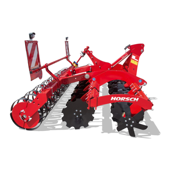
Page 31: Construction
Construction Overview 1 Three-point implement attachment 2 Depth setting scale 3 Depth setting (Fig.: hydraulic) 4 Lighting 5 Packer (Fig.: Cage roller) 6 Side limitation 7 DiscSystem 8 Spade disc... -
Page 32: Hydraulics
Hydraulics Identification of hydraulic WARNING hoses Unintentional hydraulic movements may lead to severe accidents and injuries! The symbol is always located above the hose that requires pressure to bring the machine in Secure or lock the control units on the tractor. ¾... - Page 33 Hydraulic depth adjustment Joker 3 CT / 3.5 CT / 4 CT rigid 1 Tractor hydraulic coupling 2 Restrictor ø 0.8 mm 3 Double acting lock valve 4 Lock valve 5 Pressure accumulator 6 Depth adjustment hydraulic cylinder Hydraulic depth adjustment Joker 4/5/6 CT 1 Tractor hydraulic coupling 2 Restrictor ø...
- Page 34 Wings Joker 4/5/6 CT 1 Tractor hydraulic coupling 2 Double acting lock valve 3 Restrictor ø 1 mm 4 Hydraulic cylinders for valves...
-
Page 35: Aluminium Clips
Aluminium clips NOTE The aluminium clips are placed on the piston Pay attention to the ratio on the machine, see ¾ rods of hydraulic cylinders, depending on the Depth setting. operating states, see chapter Operation. Different aluminium clips The thickness of the clips differs according to colour: Colour blue... -
Page 36: Lighting
Lighting Instruction stickers Clean soiled stickers. ¾ Damaged or illegible stickers must be re- ¾ placed immediately. Apply the specified stickers to spare parts. ¾ Lock valve (1) open (2) closed 7-pin plug Rear light, right Lamp, blinker Lamp, taillight Lamp, brake light Rear light, left Lamp, brake light... -
Page 37: Operation
Operation Connecting Connecting/Parking NOTE Observe the permissible total weight of the ¾ tractor, the maximum lifting force, the permis- sible axle loads as well as the weight distribu- DANGER Ballasting Technical data tion, see chapter There is a risk that persons may become Check all plug-and-socket connections (hy- crushed and severely injured between machine ¾... -
Page 38: Adjust Connecting Mechanism To Tractor
Adjust connecting mechanism to 5. Couple the upper link and secure the bolt with the cotter pin. Use the position fitting for the tractor respective tractor. The bolt is correctly positioned when the ma- Joker 3 CT/3.5 CT: chine is at maximum working depth and the upper link slightly rises toward the machine. -
Page 39: Transport Position
Transport position NOTE Make sure before driving on public roads that ¾ WARNING the machine meets all respective applicable Danger of traffic accidents caused by overwidth national road traffic regulations. of machine Joker 3 CT /3.5 CT: Folding in the side limita- Make the following additional adjustments be- ¾... -
Page 40: Parking
Parking Valves (Joker 4/5/6 CT) DANGER WARNING Serious accidents caused by the machine roll- Dropping or lowering machine parts can cause ing away! severe crushing injuries etc.! Park the machine only on a flat, paved sur- No persons may stay under raised machine ¾... -
Page 41: Depth Setting
Depth setting Hydraulic depth setting With the hydraulic depth setting one can adjust In working position the packer carries the weight the working depth in the field and during use. of the machine. The working depth is adjusted The hydraulic depth setting is ideally combined on the packer. -
Page 42: Side Limitation
Side limitation WARNING The side limitation has the function to prevent The hydraulic system is under high pressure. the formation of a barrier at the adjoining track. Hydraulic oil escaping under pressure can pen- The side limitation is adjustable in height and etrate the skin and cause serious injuries. -
Page 43: Use In The Field
Use in the field Checks The working quality essentially depends on the adjustments and checks made prior to and dur- NOTE ing use, as well as on regular care and mainte- nance of the machine. Please note: Do not drive backwards with the machine Carry out all maintenance tasks and adjust- •... -
Page 44: Assembly Groups
Assembly groups Maintenance The bearings of the discs are filled with grease ¾ and therefore principally maintenance-free. DiscSystem Check the bearings regularly for clearance, leak tightness and even running after extend- ed idle times. In case of loose or already worn discs, tighten ¾... -
Page 45: Packer
Generally, clean the packer before starting ¾ road travel. Cage roller Depth guidance with moderate consolidation. Particularly recommendable for very light soils or if the Joker CT is to be kept as light as possible - e.g. when connecting a liquid manure wagon. -
Page 46: Cage Roller Large (Ø 64 Cm)
Cage roller large (Ø 64 cm) RollFlex Packer Cage roller large RollFlex Packer Excellent self-cleaning under moist conditions. Good depth guidance on very light soils. Par- Consolidation in strips with high mixing effect ticularly recommended for soils with a tendency and a very high levelling potential. -
Page 47: Rollcut Packer
RollCut Packer Maintenance Check packer bearings for tight fit. ¾ Check packer shafts for free rotation. ¾ Lubricate the packer bearings at regular in- ¾ tervals. Check packer segments for wear, deformation ¾ and breakage. Only for tyre packers: Check wheels for tight fit. ¾... -
Page 48: Optional Equipment
Optional equipment Preparation set for liquid manure installation Hydraulic depth setting The Joker CT can be equipped with a bracket for fastening a liquid manure spreading system. See chapter Depth setting. Additional weights The Joker CT can be equipped with additional weights. -
Page 49: Harrow
Harrow The Joker can be equipped with a harrow at the rear (option). The harrow loosens and levels the surface and distributes existing harvest residues. With the two bolts (see arrow) in front of and behind the pivot point the harrow movement can be limited upwards and downwards. -
Page 50: Care And Maintenance
Care and Cleaning Maintenance Perform regular cleaning and maintenance work in order to maintain the operability of the machine and to achieve optimal performance. WARNING NOTE Risk of injuries during maintenance work Do not clean hydraulic cylinders and bearings Please observe the safety notes on care and ¾... -
Page 51: Maintenance Intervals
Maintenance intervals The maintenance intervals are determined by various factors. Different application conditions, weather influ- ences, working speeds and soil conditions have an influence on the maintenance intervals. The quality of the lubricants and cleaning agents also affects the time to the next care activities. The specified maintenance intervals therefore only serve as a reference. -
Page 52: Maintenance Overview
Maintenance overview Joker CT Maintenance location Work instructions Interval After 10 operating hours Retighten all screw and plug-in Even firmly tightened screw connections can come loose (e.g. Once connections as well as the hydraulic because of material settlement or paint residues between the connections. - Page 53 Maintenance location Work instructions Interval Joker CT Frame and frame connecting parts Check condition and firm seating 40 h (see torque table) Discs Check for condition, firm seating and wear, daily Check oil bath bearing for leak tightness and wear...
- Page 54 Lubrication points (lubrication grease: DIN 51825 KP/2K-40) - Lubricate the following, number of lubrication points in brackets Valve joints lubricate (4) daily Mounting of side limitation lubricate (2) daily RollCut packer screw adjustment lubricate (2) daily Lubrication points with the addition “2x” can be found on either side of the machine. Joker 4/5/6 CT...
-
Page 55: Waste Disposal
Attention must be paid to all valid regulations. Decommissioning and waste disposal must only be carried out by operators who have been trained by HORSCH. Contact a waste disposal company, if this should be necessary. -
Page 56: Appendix
Appendix Tightening torques NOTE The tightening torques only serve as guidelines and are generally valid. Actual data given at the • corresponding points in the operating instructions have priority. Screws and nuts must thereby not be treated with lubricant, since this would change the friction value. •... - Page 57 Inch screws Tightening torques - inch screws in Nm Screw Strength 2 Strength 5 Strength 8 diameter No marks on head 3 marks on head 6 marks on head Inch Coarse Fine thread Coarse Fine thread Coarse Fine thread thread thread thread 12.2...
-
Page 58: Index
Index Accessories 6 Harrow 45 Additional weights 44 Headland 39 Aluminium clips 31 Height 18 High pressure cleaner 46 Hydraulic depth setting 37 Brake system 11 Hydraulics 10,24,48 Cable 32 Installation 17 Cage roller 41 Care 13,46 Children 8 Length 18 Cleaning 46 Liability 4 Cleaning, coulter discs 40... - Page 59 Safety 6 Safety stickers 15,49 Screw connections 13 Service 5 Side limitation 27,38,49 Spade disc 27 Spare parts 6 Speed 9 SteelDisc Packer 42 Stickers 15,32 Storage 47 Technical data 18 Three-point 23,27 Traffic 8 Transport 8,17 Transport height 18 Transport position 35 Transport width 8,18 Type approval 9...
- Page 61 All details on technical specifications and pictograms are approximate and for information only. Subject to technical product revisions. HORSCH Maschinen GmbH Tel.: +49 94 31 7143-0 Sitzenhof 1 Fax: +49 94 31 7143-9200 92421 Schwandorf E-Mail: info@horsch.com www.horsch.com...
Need help?
Do you have a question about the Joker CT and is the answer not in the manual?
Questions and answers