Table of Contents
Advertisement
Quick Links
Reference Manual
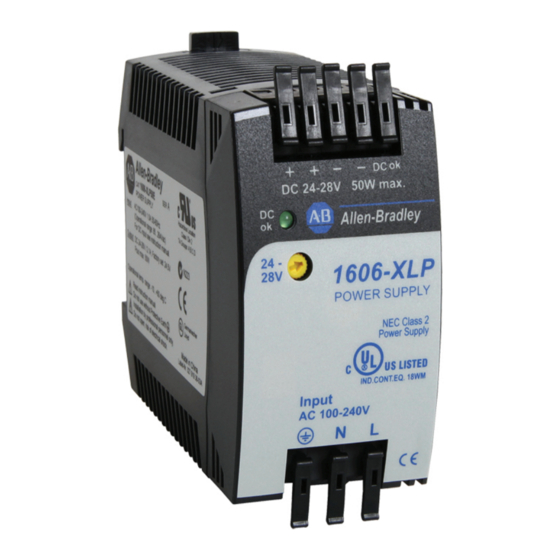
Bulletin 1606 Switched Mode Power Supplies
Catalog Number: 1606-XLP50E
Index
1.
Description ........................................................1
Specification Quick Reference ............................1
2.
3.
Catalog Numbers ................................................1
4.
Certification Marks ..............................................1
5.
AC-Input...............................................................4
6.
Input Inrush Current Surge .................................5
7.
DC-Input...............................................................5
8.
Hold-up Time.......................................................6
9.
DC-OK Output .....................................................6
10. Output .................................................................7
11. Efficiency and Power Losses................................8
12. Functional Diagram.............................................9
13. Reliability .............................................................9
14. Front Side and User Elements...........................10
15. Terminals and Wiring........................................10
16. EMC....................................................................11
17. Environment ......................................................12
18. Protection Features ...........................................12
19. Safety .................................................................13
20. Dielectric Strength ............................................13
Terminology and Abbreviations
• PE and
symbol-PE is the abbreviation for Protective Earth and has the same meaning as the symbol
• Earth, Ground-This document uses the term "earth" which is the same as the U.S. term "ground".
• T.b.d.-To be defined, value or description will follow later.
• AC 230V-A figure displayed with the AC or DC before the value represents a nominal voltage with standard tolerances (usually ±15%)
included. E.g.: DC 12V describes a 12V battery disregarding whether it is full (13.7V) or flat (10V)
• 230Vac-A figure with the unit (Vac) at the end is a momentary figure without any additional tolerances included.
• 50Hz vs. 60Hz-As long as not otherwise stated, AC100V and AC230V parameters are valid at 50Hz and AC120V parameters are valid at 60Hz
mains frequency.
• may-A key word indicating flexibility of choice with no implied preference.
• shall-A key word indicating a mandatory requirement.
• should-A key word indicating flexibility of choice
21. Certifications .................................................... 14
22. Environmental Compliance ............................. 14
23. Physical Dimensions and Weight ..................... 15
24. Installation and Operation Instructions .......... 15
25. Accessory........................................................... 16
26. Application Notes............................................. 17
26.1. Peak Current Capability ......................... 17
26.2. Back-feeding Loads ................................ 17
26.3. Series Operation..................................... 18
26.5. Parallel Use for Redundancy.................. 18
26.6. Daisy Chaining of Outputs..................... 19
26.8. External Input Protection....................... 20
26.9. Inductive and Capacitive Loads ............. 20
26.10. Operation on Two Phases ...................... 20
26.11. Use in a Tightly Sealed Enclosure .......... 20
26.12. Mounting Orientations .......................... 21
............................. 19
.
Advertisement
Table of Contents

Related Manuals for Allen-Bradley Bulletin 1606


Summary of Contents for Allen-Bradley Bulletin 1606
-
Page 1: Table Of Contents
Reference Manual Bulletin 1606 Switched Mode Power Supplies Catalog Number: 1606-XLP50E Index Description ............1 21. Certifications ............ 14 Specification Quick Reference ......1 22. Environmental Compliance ......14 Catalog Numbers ..........1 23. Physical Dimensions and Weight ..... 15 Certification Marks ..........1 24. - Page 2 Bulletin 1606 Switched Mode Power Supplies Power Supply • AC 100-240V Wide Range Input • NEC Class 2 Compliant • Adjustable Output Voltage • Efficiency up to 89% • Compact Design, Width only 45mm • Full Output Power Between -10°C and +60°C •...
- Page 3 Bulletin 1606 Switched Mode Power Supplies Intended Use • This device is designed for installation in an enclosure and is intended for the general professional use such as in industrial control, office, communication, and instrumentation equipment. • Do not use this power supply in aircraft, trains, nuclear equipment or similar systems where malfunction may cause severe personal injury or threaten human life.
-
Page 4: Ac-Input
Bulletin 1606 Switched Mode Power Supplies 5. AC-Input AC input nom. AC 100-240V Wide-range input, TN-, TT-, IT-Mains, see Fig. 5-1 AC input range 85-264Vac Continuous operation 60-85Vac Full power for 200ms, no damage between 0 and 85Vac 264-300Vac < 0.5s Input frequency nom. -
Page 5: Input Inrush Current Surge
Bulletin 1606 Switched Mode Power Supplies 6. Input Inrush Current Surge A NTC limits the input inrush current after turn-on of the input voltage. The inrush current is input voltage- and ambient temperature-dependent. AC 100V AC 120V AC 230V Inrush current max. -
Page 6: Hold-Up Time
Bulletin 1606 Switched Mode Power Supplies 8. Hold-up Time AC 100V AC 120V AC 230V Hold-up Time typ. 54ms 82ms 360ms 1.05A, 24V, see Fig. 8-1 typ. 26ms 40ms 180ms 2.1A, 24V, see Fig. 8-1 Fig. 8-1 Hold-up time vs. input voltage Fig. -
Page 7: Output
Bulletin 1606 Switched Mode Power Supplies 10. Output Output voltage nom. Adjustment range 24-28V Guaranteed min. max. At clockwise end position of potentiometer Factory setting at full load, cold unit 24.5V ±0.2%, Line regulation max. 10mV 85 to 264Vac Load regulation max. -
Page 8: Efficiency And Power Losses
Bulletin 1606 Switched Mode Power Supplies 11. Efficiency and Power Losses AC 100V AC 120V AC 230V 88.4% 89.0% 2.1A, 24V Power losses 1.05A, 24V 2.1A, 24V Fig. 11-1 Efficiency vs. output current at 24V Fig. 11-2 Losses vs. output current at 24V... -
Page 9: Functional Diagram
Bulletin 1606 Switched Mode Power Supplies 12. Functional Diagram Fig. 12-1 Functional diagram Input Rectifier Input Fuse Power Output & & Converter Filter Inrush Input Filter Limiter DC-OK DC-ok Transistor Output Over- Signal Signal Voltage Protection Output Voltage Regulator 13. Reliability These units are extremely reliable and use only the highest quality materials. -
Page 10: Front Side And User Elements
Bulletin 1606 Switched Mode Power Supplies 14. Front Side and User Elements Fig. 14-1 Front side DC-OK LED (green) Output & Signal Terminals Spring-clamp terminals On when the voltage at the Dual terminals per pole output terminals is > 20 V... -
Page 11: Emc
Bulletin 1606 Switched Mode Power Supplies 16. EMC The CE mark indicates conformance with EMC guideline 89/336/EEC, 93/68/EEC and the low-voltage directive (LVD) 73/23/EWG. EN 61000-6-2, EN 61000-6-1 Generic standards EMC Immunity Electrostatic discharge EN 61000-4-2 Contact discharge Criterion A... -
Page 12: Environment
Bulletin 1606 Switched Mode Power Supplies 17. Environment Operational temperature -10°C to +70°C (14°F to 158°F) Reduce output power according to Fig. 17-1 C ° C ° F ° ) F ° Fig. 17-1 Storage temperature -40 to +85°C (-40°F to 185°F) -
Page 13: Safety
Bulletin 1606 Switched Mode Power Supplies 19. Safety Input / output separation SELV IEC/EN 60950-1 forced insulation i t c Isolation resistance > 5MOhm input to output, 500Vdc Touch current (leakage current) typ. 0.12mA 100Vac, 50Hz, TN mains < <... -
Page 14: Certifications
Bulletin 1606 Switched Mode Power Supplies 21. Certifications EN 60950-1, Complies with CE EMC and CE Low Voltage Directives EN 61204-3 UL 508 LISTED as Industrial Control Equipment E198865 IND. CONT. EQ. UL 60950-1 RECOGNIZED E168663 recognized for use in the U.S.A. (UL 60950-1) and Canada (C22.2 No. -
Page 15: Physical Dimensions And Weight
Bulletin 1606 Switched Mode Power Supplies 23. Physical Dimensions and Weigth Weight 240g / 0.53lb DIN Rail Use 35mm DIN rails according to EN 60715 or EN 50022 with a height of 7.5 or 15mm. The DIN rail height must be added to the de pth (91mm) to calculate the total required installation depth. -
Page 16: Accessory
Bulletin 1606 Switched Mode Power Supplies 25. Accessory DIN Rail bracket for wall or panel mount A DIN rail bracket is included in each shipping box. Fig. 25-1 DIN Rail Bracket Dimensions Hole diameter: 4.2mm 1606-XLPRED Dual decoupling module 2x5A Redundant System with two 1606-XLP50E Fig. -
Page 17: Application Notes
Bulletin 1606 Switched Mode Power Supplies 26. Application Notes 26.1. Peak Current Capability Solenoids, contactors and pneumatic modules often have a steady state (sealed) coil and a pick-up coil. The inrush current demand of the pick-up coil is several times higher than the steady state curre nt and usually exceeds the nominal output current. -
Page 18: Series Operation
Bulletin 1606 Switched Mode Power Supplies 26.3. Series Operation The power supply can be put in series to increase the output voltage. Instructions for use in series: Fig. 26-3 Schematic for series operation It is possible to connect as many units in series as needed,... -
Page 19: Daisy Chaining Of Outputs
Bulletin 1606 Switched Mode Power Supplies Please note: This simple way to build a redundant system has two major disadvantages. The faulty power supply cannot be identified. The green LED will still be on since it is reverse-powered from the other power supply. -
Page 20: External Input Protection
Bulletin 1606 Switched Mode Power Supplies 26.8. External Input Protection The unit is tested and approved for branch circuits up to 15A (UL) or 16A (IEC). External protection is required only if the supplying branch has an ampacity greater than this. In some countries, local regulations may apply, so check local codes and requirements. -
Page 21: Mounting Orientations
Bulletin 1606 Switched Mode Power Supplies 26.12. Mounting Orientations Mounting orientations other than input terminals on the bottom and output on the top require a reduction in continuous output power or a limitation in the maximum allowed ambient temperature. The amount of reduction influences the lifetime expectancy of the power supply. - Page 22 Rockwell Automation Support Rockwell Automation provides technical information on the Web to assist you in using its products. At http://www.rockwellautomation.com/support, you can find technical manuals, technical and application notes, sample code and links to software service packs, and a MySupport feature that you can customize to make the best use of these tools.
Need help?
Do you have a question about the Bulletin 1606 and is the answer not in the manual?
Questions and answers