Table of Contents
Advertisement
Quick Links
Advertisement
Table of Contents

Subscribe to Our Youtube Channel
Related Manuals for Black Horse Model MESSERSCHMITT BF-109E


Summary of Contents for Black Horse Model MESSERSCHMITT BF-109E
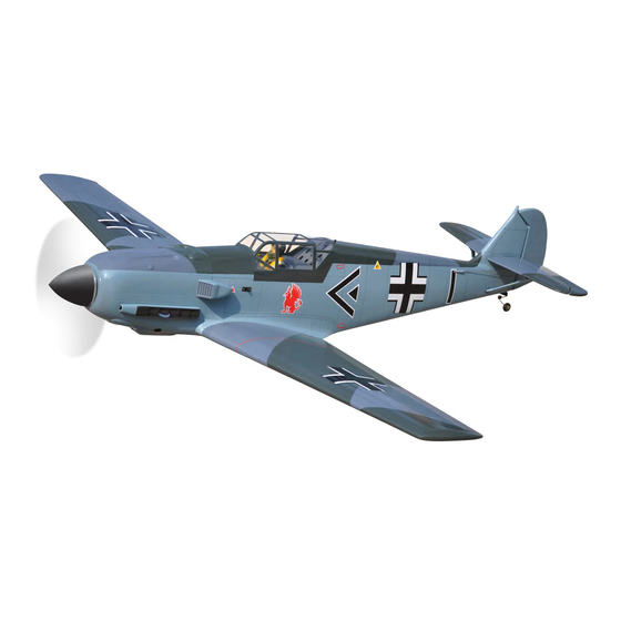
- Page 1 Instruction Manual Book ITEM CODE: BH109 SPECIFICATION 1 Wingspan : 2,200mm. 86.61 in. 1 Length : 1,976 mm. 77.80 in. 1 Weight : 8.3 kg. 18.26 lbs. Part listing required (not included): 1 Glow Engine : 55 CC Gas 1 Servo: 09 standard high torque servos. 1 Radio: 07 channels.
- Page 2 MESSERSCHMITT BF-109E - Instruction Manual Item code:BH109 . This instruction manual is designed to help you build a great flying aeroplane. Please read this manual thoroughly before starting assembly of your MESSERCHMITT BF-109E. Use the parts listing below to identify all parts.
-
Page 3: Safety Precaution
MESSERSCHMITT BF-109E - Instruction Manual Item code:BH109 . Caution: this model is not a toy! If you are a beginner to this type of powered model, please ask an experienced model flyer for help and support. If you attempt to operate the model without knowing what you are doing you could easily injure yourself or somebody else. -
Page 4: Installing The Aileron Servos
MESSERSCHMITT BF-109E - Instruction Manual Item code:BH109 . REPLACEMENT SMALL PARTS 3 x 15mm. 3 x 15mm. 3 x 15mm. 5x40mm. 5x40mm. 5 x 70mm. 1.Door mounting wheel. I. AILERON. 2. Air retract main gear. 3. Wheels. 1.INSTALLING THE AILERON SERVOS. - Page 5 MESSERSCHMITT BF-109E - Instruction Manual Item code:BH109 . 5. Instal servo tray with aileron servo into the wing as same as picture below. 2x10mm. 3. Using the thread as a guide and using masking tape, tape the servo lead to the end of the thread: carefully pull the thread out.
-
Page 6: Installing The Flap Servos
MESSERSCHMITT BF-109E - Instruction Manual Item code:BH109 . II. FLAP. 1.INSTALLING THE FLAP SERVOS. Aileron control horn. thread INSTALLING THE AILERON LINKAGES. Installing the aileron linkages as pictures below. 3x10mm. 75mm Electric 3x10mm 2x10mm. Secure. Secure. 2.INSTALLING THE FLAP 2. INSTALLING THE FLAP CONTROL HORN. - Page 7 MESSERSCHMITT BF-109E - Instruction Manual Item code:BH109 . Secure. A+B EPOXY PLUS glue Flap 4x12mm Flap control horn. 3.INSTALLING THE FLAP LINKAGES . Installing the flap linkages as pictures below. 3x10mm. 75mm.
- Page 8 MESSERSCHMITT BF-109E - Instruction Manual Item code:BH109 . Secure. 3x4mm. 3x6mm. Bottom side. Aileron. Flap Repeat the procedure for the other wing half. INSTALLING AIR RETRACTABLE LANDING GEAR. 3x15mm. 3x15mm. 5x40mm. 5x40mm.
- Page 9 MESSERSCHMITT BF-109E - Instruction Manual Item code:BH109 . 5x40mm. Secure. 3 x 15 mm. Secure. 3x4mm 3 x 6 mm Secure. Secure 3x4mm.
- Page 10 MESSERSCHMITT BF-109E - Instruction Manual Item code:BH109 . Secure 3x4mm. Plastic Parts For Bottom Wing. 3x20mm. 3x15mm. Drill a hole 3.5mm diameter Drill a hole 3.5mm diameter Drill a hole 3.5mm diameter Secure 3x6mm. 3x20mm.
-
Page 11: Installing The Engine Mount
MESSERSCHMITT BF-109E - Instruction Manual Item code:BH109 . Secure. Bottom side. Repeat the procedure for the other wing half. INSTALLING THE ENGINE MOUNT. See pictures below: 3x15mm. Drill a hole 3mm diameter Secure. -
Page 12: Installing The Engine
MESSERSCHMITT BF-109E - Instruction Manual Item code:BH109 . INSTALLING THE ENGINE. INSTALLING THE THROTTLE - CABLE. 1. Install one adjustable metal connector 5 x 70 mm through the third hole out from the center of one servo arm, enlarge the hole in the servo arm using a 2mm drill bit to accommodate the servo connector. -
Page 13: Installing The Stopper Assembly
MESSERSCHMITT BF-109E - Instruction Manual Item code:BH109 . When the stopper assembly is installed in the tank, the top of the vent tube should rest just below the top surface of the tank. It should not touch the top of the tank. - Page 14 MESSERSCHMITT BF-109E - Instruction Manual Item code:BH109 . Left side. 1 7) Using a modeling knife, cut 3 lengths of fuel line 150mm long. Connect 2 lines to the 2 COWLING. vent tubes and 1 line to the fuel pickup tube in the stopper.
- Page 15 MESSERSCHMITT BF-109E - Instruction Manual Item code:BH109 . Left side Bottom side Trim and cut Right side Drill a hole Machine 2.5mm diameter screw. Drill a hole 2.5mm B o t t o m side. 3 x 12mm Front view...
-
Page 16: Installing The Spinner
MESSERSCHMITT BF-109E - Instruction Manual Item code:BH109 . INSTALLING THE SPINNER. See pictures below Aluminium tube 10 mm 5x 70mm Front view Secure. Secure. Length 49mm. 5x 70mm. -
Page 17: Horizontal Stabilizer Installation
MESSERSCHMITT BF-109E - Instruction Manual Item code:BH109 . HORIZONTAL STABILIZER INSTALLATION. Horizontal stabilizer installation . See picture below. 3x 15 mm 3x 25 mm 12 mm 255 mm Secure 3x 15 mm Secure. -
Page 18: Elevator Control Horn Installation
MESSERSCHMITT BF-109E - Instruction Manual Item code:BH109 . Secure. Elevator control horn. ELEVATOR PUSHROD INSTALLATION. ELEVATOR CONTROL HORN INSTALLATION. Elevator pushrod install as same as the way of aileron pushrod. Elevator control horn install as same as the way of aileron control horn. Please see pic- tures below. -
Page 19: Horizontal Stabilizer Struts
MESSERSCHMITT BF-109E - Instruction Manual Item code:BH109 . Bottom side. Bottom side. Elevator pushrod. Elevator Elevator pushrod pushrod E l e v a t o r pushrod. HORIZONTAL STABILIZER STRUTS. RUDDER SERVO INSTALLATION. Rudder servo install as same as method of 3 x 25mm elevator servo. -
Page 20: Rudder Installation
MESSERSCHMITT BF-109E - Instruction Manual Item code:BH109 . Rudder cable. RUDDER INSTALLATION. Please see pictures below. Rudder. Secure. Aluminium... -
Page 21: Rudder Control Horn Installation
MESSERSCHMITT BF-109E - Instruction Manual Item code:BH109 . RUDDER CONTROL HORN INSTALLATION. Rudder control horn install as same as the way of aileron control horn. Please see pic- tures below. Push. Control horn of Rudder. Aluminium Aluminium A+B Epoxy PLUS glue Cut. -
Page 22: Rudder Cable Installation
MESSERSCHMITT BF-109E - Instruction Manual Item code:BH109 . Plastic part for tail gear. RUDDER CABLE INSTALLATION. Rudder push-pull system install as sams as picture below 3x10mm Secure. Bottom side. C/A glue. C/A glue. tail gear. - Page 23 MESSERSCHMITT BF-109E - Instruction Manual Item code:BH109 . INSTALLATION SERVO AIR RETRACT- ABLE LANDING GEAR . Valve control Valve one way Air tank 3 way conector Air tank Air supply Valve one way Right main gear wing Left main gear wing...
-
Page 24: Installing The Switch
MESSERSCHMITT BF-109E - Instruction Manual Item code:BH109 . INSTALLATION AIR TANK Air tank Secure. INSTALLING THE SWITCH. 1 1) Cut out the switch hole using a modeling knife. Use a 2mm drill bit and drill out the two mounting holes through the fuselage side. - Page 25 MESSERSCHMITT BF-109E - Instruction Manual Item code:BH109 .
-
Page 26: Wing Attachment
MESSERSCHMITT BF-109E - Instruction Manual Item code:BH109 . Battery of Switch of engine Receiver INSTALLING THE RECEIVER AND BATTERY. 1 1. Plug the servo leads and the switch lead into the receiver. You may want to plug an aileron extension into the receiver to make plugging in the aileron servo lead easier when you are installing the wing . -
Page 27: Installing Cockpit Fuselage
MESSERSCHMITT BF-109E - Instruction Manual Item code:BH109 . Secure. Right wing Secure INSTALLING COCKPIT FUSELAGE . 1 3.Insert two wing panels as pictures below. See picture below: Left wing... - Page 28 MESSERSCHMITT BF-109E - Instruction Manual Item code:BH109 . See picture wing attach to fuselage. A+B Epoxy Installing the fuselage hatch as same as pic- PLUS glue. ture below. C/A glue. Top side. C/A glue. BALANCING. 1 1) It is critical that your airplane be bal- anced correctly.
-
Page 29: Control Throws
MESSERSCHMITT BF-109E - Instruction Manual Item code:BH109 . Accurately mark the balance point on the top CONTROL THROWS. of the wing on both sides of the fuselage. The 4 1) We highly recommend setting up a balance point is located 135mm back from the leading edge. -
Page 30: Pre-Flight Check
4 4) Check the control surface. 4 5) Check the receiver antenna . It should be fully extended and not coiled up inside the fuselage. 4 6) Properly balance the propeller. We wish you many safe and enjoyable flights with your Messerschmitt BF-109E.
Need help?
Do you have a question about the MESSERSCHMITT BF-109E and is the answer not in the manual?
Questions and answers