Sign In
Upload
Manuals
Brands
Kikusui Manuals
Measuring Instruments
TOS9301
Kikusui TOS9301 Manuals
Manuals and User Guides for Kikusui TOS9301. We have
2
Kikusui TOS9301 manuals available for free PDF download: User Manual
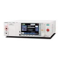
Kikusui TOS9301 User Manual (340 pages)
Electrical Safety Analyzer
Brand:
Kikusui
| Category:
Measuring Instruments
| Size: 18 MB
Table of Contents
About Manuals
3
Open Source Software
3
Accessories
4
Product Overview
4
Notations Used in this Manual
5
Safety Precautions
5
Notes on Usage
6
Table of Contents
7
Component Names
12
Safety Precautions for Testing
19
Lighting of the DANGER LED
19
Test Precautions
19
Pre-Test Precautions
19
Testing Precautions
20
Precautions When Setting Test Conditions
20
Precautions after Output Has Been Turned Off21
21
Estimated Discharge Time
21
Remote Control Precautions
22
Malfunction Precautions
22
Dangerous Malfunctions
22
Emergency Measures
22
Protection Functions
23
Installation
25
Connecting the Power Cord
25
Checking Whether the Power Is on or off
26
Checking the Interlock Operation
26
Turning the Power on
27
Turning the Power off
28
Setting Date
28
Connection for Withstanding Voltage and Insulation Resistance Tests
29
Connecting the Test Leads
29
Removing the Test Leads
33
Connection for Earth Continuity Tests
34
Four-Terminal Wiring and Two-Terminal Wiring
34
Connecting the Test Leads
35
Removing the Test Leads
37
Connection for Partial Discharge Tests
38
Connecting the Test Leads
38
Removing the Test Leads
40
Connection for Leakage Current Tests
41
Using the Insulation Transformer
41
Connecting the EUT to the Power Supply
41
Connecting the Test Leads
44
Basic Operation
46
Basic Panel Operations
46
Switching Menus
46
Using the Function Keys
47
Inputting Numbers and Characters
49
Changing Values
50
Selecting the Test Mode
51
Selecting the Test Mode
52
Withstanding Voltage and Insulation Resistance Tests
53
Setting Test Conditions
53
Displaying the Setup Screen (Home Menu)
53
Description of Test Conditions
54
Test Voltage
55
Limit Voltage
56
Start Voltage
57
End Voltage
58
Frequency
59
Upper Limit
60
Lower Limit
61
Unit of Criteria (Judge Type)
62
Auto Setting of the Judgment Delay (Delay Auto)
63
Test Time
65
Voltage Rise Time
66
Voltage Fall Time
67
Discharge Time
68
Discharge When Interlock Is Activated (Discharge Interlock)
69
Current Detection Response Speed (Filter)
70
Grounding Mode (GND)
71
Current Measurement Mode (Current RMS)
73
Voltage Measurement Mode (Volt Measure)
74
Using the Low-Pass Filter
75
Peak Value Display (Display Peakhold)
76
Offset (Offset Real, Offset Imag)
77
Offset
78
Checking the Scanner Contact (Contact Check)
79
Setting Scanner Channels (Edit)
80
Opening the Scanner (All Open)
81
Starting a Test
82
Output Time Limit
82
Starting a Test
83
Patient Leakage Current
84
Operation after a Test Starts
84
Test
84
Changing the Voltage Setting During a Test
87
Finishing the Test and Viewing the Judgment
88
Stopping Tests
88
Conditions that Cause a Test to End
88
Judgment Types and Operation
89
Clearing the Judgment Result
89
Earth Continuity Test
90
Setting Test Conditions
90
Displaying the Setup Screen (Home Menu)
90
Description of Test Conditions
91
Test Current
91
Limit Current
92
Frequency
92
Upper Limit
93
Lower Limit
94
Test Time
95
Current Rise Time
96
Current Fall Time
96
Terminal Wiring Method (Terminals Wire)
97
Contact Check
98
Peak Value Display (Display Peakhold)
99
Offset
100
Starting a Test
101
Output Time Limit
101
Operation after a Test Starts
102
Changing the Current Setting During a Test
105
Finishing the Test and Viewing the Judgment106
106
Stopping Tests
106
Conditions that Cause a Test to End
106
Judgment Types and Operation
107
Clearing the Judgment Result
107
Partial Discharge Test
108
Set Test Conditions
108
Displaying the Setup Screen (HOME Menu)
108
Description of Test Conditions
109
Setting the Voltage Pattern, Test Voltages, and Application Times
110
Limit Voltage
113
Frequency
113
Upper Limit of Electric Charge (Upper Coulomb)
114
Reference Upper Limit of Discharge Count (Upper Pulse Count)
115
Threshold for Discharge (Pulse Count Threshold)
116
Measurement Range (Range)
117
Electric Charge for Detecting Discharge Inception Voltage (Inception Voltage)
118
Electric Charge for Detecting Discharge Extinction Voltage (Extinction Voltage)
119
Band Pass Filter
120
Low-Pass Filter
121
Voltage Measure
122
Electric Charge Peak Value Display (Display Peakhold)
123
Electric Charge Calibration (Precalibration)
123
Graph Scale Setting (Graph Scale)
124
Display of Discharge Inception Voltage/Discharge Extinction Voltage (Inc/Ext-Volt Marker)
125
Graph Axis Setting (Graph Format)
126
Precalibration
127
Automatically Perform Precalibration before Starting a Test
127
Manually Perform Precalibration
128
When Precalibration Fails
128
Starting a Test
129
Operation after a Test Starts
129
Changing the Voltage Setting During a Test
131
Finish the Test and Judge
132
Stopping Tests
132
Conditions that Cause a Test to End
132
Judgment Types and Operation
133
Clearing the Judgment Result
133
Touch Current Test
134
Setting Test Conditions
134
Displaying the Setup Screen (Home Menu)
134
Description of Test Conditions
135
Network
136
Polarity of the Power Supply Line
137
Single Fault Mode (Condition)
138
Probe Connection Destination
139
Output from the 110% Terminal (110% OUT)
140
Upper Limit
141
Lower Limit
142
Judgment Delay (Judge Delay)
143
Test Time
144
Measurement Range
145
Measurement Mode (Measure Mode)
147
Peak Value Display (Display Peakhold)
149
Measurement Check (Measure Check)
149
Offset
150
Voltage Conversion (Conv Voltage)
151
Checking the EUT Operation (Line OUT)
151
Starting a Test
152
Connecting the Test Leads to the EUT
152
Starting a Test
154
Operation after a Test Starts
155
Finishing the Test and Viewing the Judgment157 Stopping Tests
157
Conditions that Cause a Test to End
157
Judgment Types and Operation
158
Clearing the Judgment Result
158
Current Test
159
Setting Test Conditions
159
Displaying the Setup Screen (Home Menu)
159
Description of Test Conditions
160
Network
161
Polarity of the Power Supply Line
162
Single Fault Mode (Condition)
162
Upper Limit
163
Lower Limit
164
Judgment Delay (Judge Delay)
165
Test Time
166
Measurement Range
167
Measurement Mode (Measure Mode)
168
Peak Value Display (Display Peakhold)
170
Measurement Check (Measure Check)
170
Offset
171
Voltage Conversion (Conv Voltage)
172
Checking the EUT Operation (Line OUT)
172
Starting a Test
173
Operation after a Test Starts
174
Finishing the Test and Viewing the Judgment176 Stopping Tests
176
Conditions that Cause a Test to End
176
Judgment Types and Operation
177
Clearing the Judgment Result
177
Setting Test Conditions
178
Displaying the Setup Screen (Home Menu)
178
Description of Test Conditions
179
Network
179
Polarity of the Power Supply Line
180
Single Fault Mode (Condition)
181
Probe Connection Destination
182
Output from the 110% Terminal (110% OUT)
183
Upper Limit
184
Lower Limit
185
Judgment Delay (Judge Delay)
186
Test Time
187
Measurement Range
188
Measurement Mode (Measure Mode)
189
Voltmeter Band Expansion (Voltmeter Bandwidth)
190
Peak Value Display (Display Peakhold)
191
Measurement Check (Measure Check)
191
Offset
192
Voltage Conversion (Conv Voltage)
193
Checking the EUT Operation (Line OUT)
193
Starting a Test
194
Connecting the Test Leads to the EUT
194
Starting a Test
196
Operation after a Test Starts
197
Finishing the Test and Viewing the Judgment199
199
Stopping Tests
199
Conditions that Cause a Test to End
199
Judgment Types and Operation
200
Clearing the Judgment Result
200
Meter Mode
201
Constructing the Measurement Circuit
202
Setting Measurement Conditions
203
Displaying the Setup Screen (Home Menu)
203
Overview of Measurement Conditions
203
Network
204
Measuring Across Terminals a and B (A-B Terminal)
205
SELV Setting
206
Measurement Range
207
Measurement Mode (Measure Mode)
208
Measurement Check (Measure Check)
208
Offset
209
Output from the 110% Terminal (110% OUT)
210
Polarity of the 110% Output
211
Executing a Measurement
212
Connecting the Test Leads
212
Taking Measurements
212
Measurement Operation
213
Measurement Example (Judgment of the Parts that Can be Touched)
213
Auto Test
215
Auto Test Overview
215
Tests that Auto Test Can Run
215
Programs and Steps
215
Main Functions
216
Program Configuration
217
Displaying the Program Editing Screen
217
Creating a Program
218
Changing a Program Name
218
Deleting a Program
219
Setting Steps
220
Displaying the Step Editing Screen
220
Editing Steps
221
Program Operation Configuration
224
Fail Judgment Operation (FAIL Judgment)
224
Step Interval
225
Step Start Operation (Trigger Source)
226
EUT Power Supply (Line Output)
227
Running Auto Tests
228
Running an Auto Test
228
Behavior During the Test
229
Finishing the Test and Viewing the Judgment230
230
Stopping Tests
230
Conditions that Cause a Test to End
230
Judgment Types and Operation
231
Clearing the Judgment Result
231
Exporting and Importing Programs
232
Exporting Programs to a USB Memory Device
232
Importing Programs from a USB Memory Device
233
External Control
234
SIGNAL I/O Connector
235
Pin Arrangement
235
I/O Signal Circuit
236
Input Signal Usage Example
237
Output Signal Usage Example
237
Connecting to the SIGNAL I/O Connector
238
Activating and Releasing Interlock
239
Interlock Activation Conditions
239
Interlock Release Conditions
239
Examples of How to Use Interlock
240
Recalling from Memory
241
Starting and Stopping Tests
242
Starting a Test
242
Stopping a Test
242
Monitoring the Test Status
243
Monitoring the Test Mode
243
Monitoring the Test and Voltage Generation Status
243
Monitoring Judgment Results
244
Monitoring the Step Execution Status of Auto Tests
245
Monitoring the Activation Status of Protection Functions
245
Monitoring Measurements
246
Monitoring Current Waveforms
246
Monitoring Voltage Waveforms
246
Monitor the Discharge Waveform of Partial Discharge
247
Monitoring Electric Charge Waveforms of Partial Discharge
247
Using Option Products
248
Signal Output from the STATUS out Connector
248
Signal I/O of the REMOTE Connector
248
Memory Function
249
Saving and Recalling Test Conditions
249
How to View the Setup Memory Screen
249
Saving to the Setup Memory
250
Checking the Setup Memory Details
251
Recalling the Setup Memory
252
Viewing and Saving Test Results
253
Displaying a List of Test Results
254
Saving Test Results to a USB Memory Device
254
Clearing the List of Test Results
255
Viewing and Saving Test Data
256
Viewing Test Data
256
Saving Test Data to a USB Memory Device
257
Deleting Test Data
257
System Settings
258
Displaying and Changing CONFIG Settings
258
Panel Settings at Startup (Power On)
259
Operation When There Is no SCPI Communication (Watchdog)
260
Key Lock
262
Calibration Configuration
263
Beep Sound (Beeper)
264
Fail Mode
265
Test Start Settings
266
PASS Judgment Result Hold Time
267
STATUS out Setting (Status Output)
268
Outputting Judgment for each Step (Step END Judgment)
269
Displaying/Changing the Interface Settings
270
Displaying SCPI Errors
272
Setting the Date/Time
273
Changing Calibration Date
274
Initializing the Settings
275
Restoring the Factory Default Settings
275
Restoring the Reset Settings
276
Updating
277
Displaying the Device Information
278
Maintenance
279
Inspection
279
Pre-Inspection for Withstanding Voltage Test and Insulation Resistance Test
279
Pre-Testing the Earth Continuity Test
280
Pre-Testing the Leakage Current Test
281
Replacing Components
283
Replacing the Backup Battery
283
Replacing the Fuse
283
Periodic Calibration
284
Specifications
286
Withstanding Voltage Test Section
286
Insulation Resistance Test Section
289
Earth Continuity Test Section
294
Partial Discharge Test Section
296
Leakage Current Test Section
299
Interface
306
Other Functions
308
General Specifications
310
External Dimensions
311
Appendix
315
Default Settings and Reset Settings
315
Withstanding Voltage (ACW/DCW), Insulation Resistance (IR) Test Conditions
315
Earth Continuity (EC) Test Conditions
316
Partial Discharge (PD) Test Conditions
316
Leakage Current (LC) Test Conditions
317
Auto Test (AUTO) Settings
318
Memory Function
318
CONFIG Settings
319
Interface Settings
320
Stray Capacitance of AC Withstanding Voltage Tests
321
Timing Charts
322
Contact Check Operation
322
ACW Test (PASS Judgment)
323
ACW Test (FAIL Judgment)
324
ACW Test (Interlock)
325
Example of Partial Discharge Test
326
Calculating the Setting
326
Performing a Pre-Test Inspection
326
Performing Tests
328
Performing an Alternative Test
329
Options
330
High Voltage Scanner
330
Remote Control Box
331
DIN Adapter Cable
331
High Voltage Test Probe
332
Warning Light Unit
332
Multi-Outlet
333
Brackets
334
Troubleshooting
335
Index
337
Advertisement
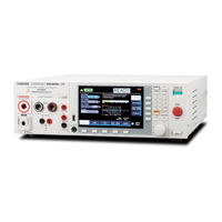
Kikusui TOS9301 User Manual (290 pages)
Electrical safety Analyzer
Brand:
Kikusui
| Category:
Measuring Instruments
| Size: 10 MB
Table of Contents
About Manuals
3
Accessories
4
Product Overview
4
Notations Used in this Manual
5
Safety Precautions
5
Notes on Usage
6
Table of Contents
7
Component Names
12
Safety Precautions for Testing
18
Lighting of the DANGER LED
18
Test Precautions
18
Pre-Test Precautions
18
Testing Precautions
19
Precautions When Setting Test Conditions
19
Precautions after Output Has Been Turned Off20
20
Estimated Discharge Time
20
Remote Control Precautions
21
Malfunction Precautions
21
Dangerous Malfunctions
21
Emergency Measures
21
Protection Functions
22
Installation
24
Connecting the Power Cord
24
Checking Whether the Power Is on or off
25
Checking the Interlock Operation
25
Turning the Power on
26
Turning the Power off
27
Connection for Withstanding Voltage and Insulation Resistance Tests
28
Connecting the Test Leads
28
Removing the Test Leads
32
Connection for Earth Continuity Tests
33
Four-Terminal Wiring and Two-Terminal Wiring
33
Connecting the Test Leads
34
Removing the Test Leads
36
Connection for Leakage Current Tests
37
Using the Insulation Transformer
37
Connecting the EUT to the Power Supply
37
Connecting the Test Leads
40
Basic Operation
42
Basic Panel Operations
42
Switching Menus
42
Using the Function Keys
43
Inputting Numbers and Characters
45
Changing Values
46
Selecting the Test Mode
47
Patient Leakage Current
47
Selecting the Test Mode
48
Withstanding Voltage and Insulation Resistance Tests
49
Setting Test Conditions
49
Displaying the Setup Screen (Home Menu)
49
Description of Test Conditions
50
Test Voltage
51
Limit Voltage
52
Start Voltage
53
Frequency
54
Upper Limit
55
Lower Limit
56
Unit of Criteria (Judge Type)
57
Auto Setting of the Judgment Delay (Delay Auto)
58
Test Time
60
Voltage Rise Time
61
Voltage Fall Time
62
Discharge Time
63
Discharge When Interlock Is Activated (Discharge Interlock)
64
Current Detection Response Speed (Filter)
65
Grounding Mode (GND)
66
Current Measurement Mode (Current RMS)
68
Voltage Measurement Mode (Volt Measure)
69
Peak Value Display (Display Peakhold)
70
Using the Low-Pass Filter
71
Offset (Offset Real, Offset Imag)
72
Offset
73
Checking the Scanner Contact (Contact Check)
74
Setting Scanner Channels (Edit)
75
Opening the Scanner (All Open)
76
Starting a Test
77
Output Time Limit
77
Starting a Test
78
Operation after a Test Starts
79
Changing the Voltage Setting During a Test
82
Finishing the Test and Viewing the Judgment
83
Stopping Tests
83
Conditions that Cause a Test to End
83
Judgment Types and Operation
84
Clearing the Judgment Result
84
Earth Continuity Test
85
Setting Test Conditions
85
Displaying the Setup Screen (Home Menu)
85
Description of Test Conditions
86
Test Current
86
Limit Current
87
Frequency
87
Upper Limit
88
Lower Limit
89
Test Time
90
Current Rise Time
91
Current Fall Time
91
Terminal Wiring Method (Terminals Wire)
92
Contact Check
93
Peak Value Display (Display Peakhold)
94
Offset
95
Starting a Test
96
Output Time Limit
96
Operation after a Test Starts
97
Changing the Current Setting During a Test
99
Finishing the Test and Viewing the Judgment100
100
Stopping Tests
100
Conditions that Cause a Test to End
100
Judgment Types and Operation
101
Clearing the Judgment Result
101
Touch Current Test
102
Setting Test Conditions
102
Displaying the Setup Screen (Home Menu)
102
Description of Test Conditions
103
Network
104
Polarity of the Power Supply Line
105
Single Fault Mode (Condition)
106
Probe Connection Destination
107
Output from the 110% Terminal (110% OUT)
108
Upper Limit
109
Lower Limit
110
Judgment Delay (Judge Delay)
111
Test Time
112
Measurement Range
113
Measurement Mode (Measure Mode)
115
Voltmeter Band Expansion (Voltmeter Bandwidth)
116
Peak Value Display (Display Peakhold)
117
Measurement Check (Measure Check)
117
Offset
118
Voltage Conversion (Conv Voltage)
119
Checking the EUT Operation (Line OUT)
119
Starting a Test
120
Connecting the Test Leads to the EUT
120
Starting a Test
121
Operation after a Test Starts
122
Finishing the Test and Viewing the Judgment124
124
Stopping Tests
124
Conditions that Cause a Test to End
124
Finishing the Test and Viewing the Judgment166
124
Judgment Types and Operation
125
Clearing the Judgment Result
125
Protective Conductor Current Test
126
Setting Test Conditions
126
Displaying the Setup Screen (Home Menu)
126
Description of Test Conditions
127
Network
128
Polarity of the Power Supply Line
129
Single Fault Mode (Condition)
129
Upper Limit
130
Lower Limit
131
Judgment Delay (Judge Delay)
132
Test Time
133
Measurement Range
134
Measurement Mode (Measure Mode)
135
Voltmeter Band Expansion (Voltmeter Bandwidth)
136
Peak Value Display (Display Peakhold)
137
Measurement Check (Measure Check)
137
Offset
138
Voltage Conversion (Conv Voltage)
139
Checking the EUT Operation (Line OUT)
139
Starting a Test
140
Operation after a Test Starts
141
Finishing the Test and Viewing the Judgment143
143
Stopping Tests
143
Conditions that Cause a Test to End
143
Judgment Types and Operation
144
Clearing the Judgment Result
144
Setting Test Conditions
145
Displaying the Setup Screen (Home Menu)
145
Description of Test Conditions
146
Network
146
Polarity of the Power Supply Line
147
Single Fault Mode (Condition)
148
Probe Connection Destination
149
Output from the 110% Terminal (110% OUT)
150
Upper Limit
151
Lower Limit
152
Judgment Delay (Judge Delay)
153
Test Time
154
Measurement Range
155
Measurement Mode (Measure Mode)
156
Peak Value Display (Display Peakhold)
158
Measurement Check (Measure Check)
158
Offset
159
Voltage Conversion (Conv Voltage)
160
Checking the EUT Operation (Line OUT)
160
Starting a Test
161
Connecting the Test Leads to the EUT
161
Starting a Test
163
Operation after a Test Starts
164
Stopping Tests
166
Conditions that Cause a Test to End
166
Judgment Types and Operation
167
Clearing the Judgment Result
167
Meter Mode
168
Constructing the Measurement Circuit
169
Setting Measurement Conditions
170
Displaying the Setup Screen (Home Menu)
170
Overview of Measurement Conditions
170
Network
171
Measuring Across Terminals a and B (A-B Terminal)
172
SELV Setting
173
Measurement Range
174
Measurement Mode (Measure Mode)
175
Measurement Check (Measure Check)
175
Offset
176
Output from the 110% Terminal (110% OUT)
177
Polarity of the 110% Output
178
Executing a Measurement
179
Connecting the Test Leads
179
Taking Measurements
179
Measurement Operation
180
Measurement Example (Judgment of the Parts that Can be Touched)
180
Auto Test
182
Auto Test Overview
182
Tests that Auto Test Can Run
182
Programs and Steps
182
Main Functions
183
Program Configuration
184
Displaying the Program Editing Screen
184
Creating a Program
185
Changing a Program Name
185
Deleting a Program
186
Setting Steps
187
Displaying the Step Editing Screen
187
Editing Steps
188
Program Operation Configuration
189
Fail Judgment Operation (FAIL Judgment)
189
Step Interval
190
Step Start Operation (Trigger Source)
191
EUT Power Supply (Line Break)
192
Running Auto Tests
193
Running an Auto Test
193
Behavior During the Test
194
Finishing the Test and Viewing the Judgment195
195
Stopping Tests
195
Conditions that Cause a Test to End
195
Judgment Types and Operation
196
Clearing the Judgment Result
196
Exporting and Importing Programs
197
Exporting Programs to a USB Memory Device
197
Importing Programs from a USB Memory Device
198
External Control
199
SIGNAL I/O Connector
200
Pin Arrangement
200
I/O Signal Circuit
201
Input Signal Usage Example
202
Output Signal Usage Example
202
Connecting to the SIGNAL I/O Connector
203
Activating and Releasing Interlock
204
Interlock Activation Conditions
204
Interlock Release Conditions
204
Examples of How to Use Interlock
205
Recalling from Memory
206
Starting and Stopping Tests
207
Starting a Test
207
Stopping a Test
207
Monitoring the Test Status
208
Monitoring the Test Mode
208
Monitoring the Test and Voltage Generation Status
208
Monitoring Judgment Results
209
Monitoring the Step Execution Status of Auto Tests
210
Monitoring the Activation Status of Protection Functions
210
Monitoring Measurements
211
Monitoring Current Waveforms
211
Monitoring Voltage Waveforms
211
Using Option Products
212
Signal Output from the STATUS out Connector.212
212
Signal I/O of the REMOTE Connector
212
Memory Function
213
Saving and Recalling Test Conditions
213
How to View the Setup Memory Screen
213
Saving to the Setup Memory
214
Checking the Setup Memory Details
215
Recalling the Setup Memory
216
Saving and Viewing Test Results
217
Displaying a List of Test Results
217
Saving Test Results to a USB Memory Device
218
Clearing the List of Test Results
218
System Settings
219
Displaying and Changing CONFIG Settings
219
Panel Settings at Startup (Power On)
220
Operation When There Is no SCPI Communication (Watchdog)
221
Screen Saver
222
Key Lock
223
Calibration Configuration
224
Beep Sound (Beeper)
225
Fail Mode
226
Test Start Settings
227
PASS Judgment Result Hold Time
228
STATUS out Setting (Status Output)
229
Outputting Judgment for each Step (Step END Judgment)
230
Displaying/Changing the Interface Settings
231
Displaying SCPI Errors
233
Setting the Date/Time
234
Initializing the Settings
235
Restoring the Factory Default Settings
235
Restoring the Reset Settings
236
Updating
237
Displaying the Device Information
238
Maintenance
239
Inspection
239
Pre-Inspection for Withstanding Voltage Test and Insulation Resistance Test
239
Pre-Testing the Earth Continuity Test
240
Pre-Testing the Leakage Current Test
241
Replacing Components
243
Replacing the Backup Battery
243
Replacing the Fuse
243
Periodic Calibration
244
Specifications
246
Withstanding Voltage Test Section
246
Insulation Resistance Test Section
249
Earth Continuity Test Section
253
Leakage Current Test Section
255
Interface
262
Other Functions
263
General Specifications
265
External Dimensions
266
Appendix
269
Default Settings and Reset Settings
269
Withstanding Voltage (ACW/DCW), Insulation Resistance (IR) Test Conditions
269
Earth Continuity (EC) Test Conditions
270
Leakage Current (LC) Test Conditions
270
Auto Test (AUTO) Settings
272
Memory Function
272
CONFIG Settings
273
Interface Settings
274
Stray Capacitance of AC Withstanding Voltage Tests
275
Timing Charts
276
Contact Check Operation
276
ACW Test (PASS Judgment)
277
ACW Test (FAIL Judgment)
278
ACW Test (Interlock)
279
Options
280
High Voltage Scanner
280
Remote Control Box
281
DIN Adapter Cable
281
High Voltage Test Probe
282
Warning Light Unit
282
Multi-Outlet
283
Brackets
284
Troubleshooting
285
Index
287
Advertisement
Related Products
Kikusui TOS9300
Kikusui TOS93 Series
Kikusui TOS9302
Kikusui TOS9303LC
Kikusui TOS9303
Kikusui TOS9320
Kikusui TOS9301PD
Kikusui TOS5301
Kikusui TOS5302
Kikusui TOS5300
Kikusui Categories
Power Supply
Test Equipment
Measuring Instruments
Racks & Stands
Controller
More Kikusui Manuals
Login
Sign In
OR
Sign in with Facebook
Sign in with Google
Upload manual
Upload from disk
Upload from URL