Table of Contents
Advertisement
Quick Links
Tel +1 (717) 767-6511
Fax +1 (717) 764-0839
www.redlion.net
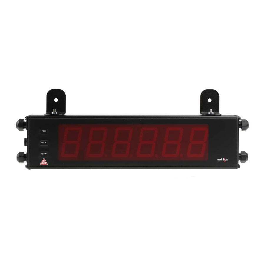
MODEL LD - LARGE STRAIN GAGE DISPLAY
GENERAL DESCRIPTION
The Large Display is a versatile display available as a strain gage meter with
scaling, serial communications and dual relay outputs. The 5 digit displays are
available in either 2.25" or 4" high red LED digits with adjustable display
intensities. The 2.25" high models are readable up to 130 feet. The 4" high
models are readable up to 180 feet. Both versions are constructed of a Type 4X/
IP65 enclosure in light weight aluminum.
All models also come with dual Form C relay outputs and RS232 / RS485
serial communications.
The Crimson software is a Windows based program that allows configuration
of the LD meter from a PC. Crimson offers standard drop-down menu
commands, that make it easy to program the meter. The meter's program can
then be saved in a PC file for future use. Crimson software can be downloaded
at www.redlion.net.
CAUTION: Risk of Danger.
Read complete instructions
prior to installation and
operation of the unit.
The protective conductor terminal is bonded to conductive
parts of the equipment for safety purposes and must be
connected to an external protective earthing system.
ORDERING INFORMATION
MODEL
DESCRIPTION
NO.
LD
2 Preset Strain Gage Input; 2.25" High 5 Digit Red LED
LD
2 Preset Strain Gage Input; 4" High 5 Digit Red LED
LD Plug Cord Grip Plug for LD models *
* Required to maintain Type 4X/IP65 specification, if end plate cord grip does not
have cable installed.
DIMENSIONS In inches (mm)
DSP
PAR
F1
F1
RST
AIR PRESSURE STABILIZATION VENT
CAUTION:
CAUTION:
Hot Surface
Risk of electric shock.
PART NUMBER
LD2SG5P0
LD4SG5P0
LDPLUG00
X
Z
MIN
MAX
1
2
TOT
2.25" & 4" HIGH RED LED DIGITS
PROGRAMMABLE SCALING AND DECIMAL POINTS
PROGRAMMABLE USER INPUT
DUAL 5 AMP FORM C RELAY
ALUMINUM TYPE 4X/IP65 CASE CONSTRUCTION
RS232/RS485 SERIAL COMMUNICATIONS
®
CRIMSON
PROGRAMMING SOFTWARE
UNIVERSALLY POWERED
SAFETY SUMMARY
All safety regulations, local codes and instructions that appear in this and
corresponding literature, or on equipment, must be observed to ensure personal
safety and to prevent damage to either the instrument or equipment connected to
it. If equipment is used in a manner not specified by the manufacturer, the
protection provided by the equipment may be impaired.
SPECIFICATIONS
1. DISPLAY: 5 digit, 2.25" (57 mm) or 4" (101 mm) intensity adjustable Red LED
(-99999 to 99999)
2. POWER REQUIREMENTS:
AC POWER: 40 to 250 VAC 50/60 Hz, 27 VA
DC POWER: 21.6 to 250 VDC, 12 W
Isolation: 3000 Vrms for 1 min.; Power IN to all inputs and outputs
3. INPUT RANGES:
INPUT
ACCURACY*
RANGE
(18 to 28 °C)
0.02% of
±24 mVDC
reading +3 µV
reading +4 µV
0.02% of
±240 mVDC
reading +30 µV
reading +40 µV
* After 20 minute warm-up. Accuracy is specified in two ways: Accuracy over
an 18 to 28 °C and 10 to 75% RH environment; and accuracy over a 0 to 65
°C and 0 to 85% RH (non-condensing environment). Accuracy over the 0 to
65 °C range includes the temperature coefficient effect of the meter.
4. CONNECTION TYPE: 4-wire bridge (differential)
2-wire (single-ended)
5. COMMON MODE RANGE (w.r.t. input common): 0 to +5 VDC
Rejection: 80 dB (DC to 120 Hz)
6. BRIDGE EXCITATION :
Jumper Selectable: 5 VDC @ 65 mA max., ±2%
10 VDC @ 125 mA max., ±2%
Temperature coefficient (ratio metric): 20 ppm/°C max.
7. A/D CONVERTER: 16 bit resolution
8. UPDATE RATES:
A/D conversion rate: 20 readings/sec.
Step response: 200 msec. max. to within 99% of final readout value
(digital filter and internal zero correction disabled)
700 msec. max. (digital filter disabled, internal zero correction enabled)
Display update rate: 1 to 20 updates/sec.
Setpoint output on/off delay time: 0 to 3275 sec.
Y
2.25
(57.15)
1
Bulletin No. LDSG-B
Drawing No. LP0914
Effective 06/16
MAX
ACCURACY*
IMPEDANCE
CONTINUOUS
(0 to 65 °C)
OVERLOAD
0.07% of
100 Mohm
30 V
0.07% of
100 Mohm
30 V
PART
X (Length)
Y (Height)
NUMBER
LD2
16 (406.4)
4 (101.6)
LD4
26 (660.4)
7.875 (200)
RESOLUTION
1 µV
10 µV
Z (Center)
12 (304.3)
22 (558.8)
Advertisement
Table of Contents

Related Manuals for red lion LD Series


Summary of Contents for red lion LD Series
-
Page 1: General Description
Bulletin No. LDSG-B Drawing No. LP0914 Effective 06/16 Tel +1 (717) 767-6511 Fax +1 (717) 764-0839 www.redlion.net MODEL LD - LARGE STRAIN GAGE DISPLAY 2.25" & 4" HIGH RED LED DIGITS PROGRAMMABLE SCALING AND DECIMAL POINTS PROGRAMMABLE USER INPUT ... -
Page 2: Installation
Contact Rating: 5 amps @ 120/240 VAC or 28 VDC (resistive load), 1/8 Max./Min. capture delay time: 0 to 3275 sec. 9. USER INPUTS: Three programmable user inputs H.P. @ 120 VAC (inductive load) Life Expectancy: 100,000 minimum operations Max. Continuous Input: 30 VDC Response Time: Isolation To Sensor Input Common: Not isolated. -
Page 3: Emc Installation Guidelines
Visit RLC’s web site at http://www.redlion.net/emi for more information on EMI guidelines, Safety and CE issues as they relate to Red Lion Controls products. WIRING OVERVIEW Electrical connections are made via pluggable terminal blocks located inside... -
Page 4: Power Wiring
3.1 POWER WIRING The power wiring is made via the 3 position terminal block (TBA) located inside the unit (right side). Power L(+) Terminal 1: VAC/DC + Terminal 2: VAC/DC - N(-) Terminal 3: Protective Conductor Terminal 3.2 INPUT WIRING Before connecting signal wires, the Range and Excitation Jumpers should be verified for proper position. -
Page 5: Serial Wiring
3.4 SERIAL WIRING RS232 Communications RS232 is intended to allow two devices to communicate over distances up to The serial connections are made via terminal block TBE located inside the 50 feet. Data Terminal Equipment (DTE) transmits data on the Transmitted Data unit on the left side for the LD2 and on the right side for the LD4. -
Page 6: Main Menu
5.0 p rograMMIng the eter OVERVIEW DISPLAY MODE PROGRAMMING MENU MAIN MENU User Input/ Display/ Signal Function Program Secondary Totalizer Setpoint Serial Factory Lock-out Function (Integrator) (Alarm) Communication Service Input Parameters Parameters Parameters Parameters Parameters Parameters Operations Parameters F1/F2 Keys 1-INP 2-FNC 3-LOC... -
Page 7: Parameter Menu
5.1 Module 1 - s Ignal nput araMeters PARAMETER MENU 1-INP rAN6E dECPt round FILtr bANd StYLE Input Display Display Filter Filter Scaling Scaling Input x Display x Range Decimal Point Rounding Setting Band Points Style Value Value SCALING POINTS INPUT RANGE ... - Page 8 DISPLAY VALUE FOR SCALING POINT 1 General Notes on Scaling 1. Input Values for scaling points should be confined to the limits of the Input Range Jumper position. 0. 0 0 2. The same Input Value should not correspond to more than one Display Value. Enter the first coordinating Display Value by using the arrow keys.
- Page 9 6.2 Module 2 - u nput and ront anel unctIon araMeters 2-FNC PARAMETER MENU USr-1 USr-2 USr-3 Sc-F1 Sc-F2 USER INPUTS FUNCTION KEYS The three user inputs are individually programmable to perform specific RELATIVE/ABSOLUTE DISPLAY meter control functions. While in the Display Mode or Program Mode, the ...
- Page 10 RESET TOTALIZER RESET, SELECT, ENABLE MINIMUM DISPLAY When activated (momentary action), the Minimum value is set to the present Input Display value. Minimum continues from that value while active (maintained action). When the user input is released, Minimum detection stops and holds When activated (momentary action), flashes and the Totalizer resets to...
- Page 11 6.3 Module 3 - d Isplay and rograM araMeters PARAMETER MENU 3-LOC SP-1 SP-2 CodE Max Display Min Display Total Display Setpoint 1 Security Setpoint 2 Lock-out Lock-out Lock-out Access Access Code MAXIMUM DISPLAY LOCK-OUT Module 3 is the programming for Display lock-out and “Full” and “Quick” Program lock-out.
- Page 12 6.4 Module 4 - s econdary unctIon araMeters PARAMETER MENU 4-SEC HI-t LO-t dSP-t At-t At-b b-LIt OFFSt Max. Capture Min. Capture Display Update Auto-Zero Auto-Zero Units Label Display Offset Delay Time Delay Time Time Tracking Delay Tracking Band BackLight Value Time...
- Page 13 6.5 Module 5 - t otalIzer ntegrator araMeters 5-tOt PARAMETER MENU dECPt tbASE SCFAC Locut P-UP Totalizer Totalizer Totalizer Totalizer Low Totalizer Power Decimal Point Time Base Scale Factor Cut Value Up Reset TOTALIZER HIGH ORDER DISPLAY The totalizer accumulates (integrates) the Input Display value using one of two modes.
-
Page 14: Setpoint Select
6.6 Module 6 - s etpoInt larM araMeters PARAMETER MENU 6-SPt SPSEL ACt-n SP-n Src-1 HYS-n tON-n tOF-n out-n rSt-n Stb-n LIt-n Setpoint Setpoint Setpoint Setpoint Setpoint On Time Off Time Output Reset Standby Setpoint Select Action Value Assignment Hysteresis Delay Delay... - Page 15 Figures. The “on” alarm may be manually reset (off) immediately by a front SETPOINT VALUE panel function key or user input.The alarm remains reset off until the trigger point is crossed again. = Latch with immediate reset action; This action latches the alarm ...
- Page 16 6.7 Module 7 - s erIal oMMunIcatIons araMeters PARAMETER MENU 7-SrL 6roSS tArE bAUd dAtA Addr Abrv HILO SPNt Print Gross Print Tare Print Max Print Setpoint Baud Data Parity Meter Abbreviated Print Print Input Print Total Rate Address Printing Options Value...
- Page 17 Sending Commands and Data Command String Construction The command string must be constructed in a specific sequence. The meter When sending commands to the meter, a string containing at least one does not respond with an error message to illegal commands. The following command character must be constructed.
- Page 18 SERIAL COMMANDS FOR LD SOFTWARE (CSR) Control Status Register Writing a “1” to bit 4 of CSR selects manual mode. In this mode, the setpoint outputs are defined by the values written to the bits b0 and b1. Internal control The Control Status Register is used to directly control the meter’s setpoint of these outputs is then overridden.
- Page 19 Communication Format Stop bit Start bit Data is transferred from the meter through a serial communication channel. In serial communications, the voltage is switched between a high and low level IDLE IDLE at a predetermined rate (baud rate) using ASCII encoding. The receiving device (8 data, no parity, 1 stop) reads the voltage levels at the same intervals and then translates the switched levels back to a character.
- Page 20 ldsg prograMMIng QuIcK overvIeW...
Need help?
Do you have a question about the LD Series and is the answer not in the manual?
Questions and answers