Table of Contents
Advertisement
Quick Links
Table of CoNTeNTS
SAFETY .................................................................................................2
SECTION 1 - INTRODUCTION ........................................................3
1-1. General ............................................................................................3
1-2. Main Components ..........................................................................4
1-3. Indicating Switch .............................................................................5
1-4. Specifications ...................................................................................6
SECTION 2 - INSTALLATION ..........................................................7
2-1. General ............................................................................................7
2-2. Mounting/Piping/DPU Installation ...............................................7
2-3. Electrical Connection (Switches/Relays) ......................................7
2-4. Switch Use .......................................................................................7
2-5. Startup..............................................................................................7
SECTION 3 - MAINTENANCE AND CALIBRATION .................9
3-1. Required Tools ................................................................................9
3-2. DPU Installation/Test/Calibration/Maintenance .........................9
3-3. Bezel/Lens (or Cover) Installation and Removal ........................9
3-4. Calibration Check .........................................................................10
3-5. Pointer Installation and Removal ................................................10
3-6. Indicator Calibration ....................................................................11
3-7. Changing Switch Setpoint ............................................................12
3-8. Complete Calibration ...................................................................14
3-9. Preventative Maintenance............................................................15
3-10. Locking Drive Arm to Torque Tube ..........................................16
3-11. Troubleshooting ..........................................................................16
SECTION 4 - INSTALLATION DRAWINGS .................................19
SECTION 5 - PARTS DRAWINGS/PARTS LISTS .........................23
[This manual is for the Indicating Switch only-refer to Model 199 DPU manual,
Part No. 10030, for detailed information about the DPU used with the indicating
switch.]
BARTON
MODEL 289A/291B
®
DIFFERENTIAL PRESSURE
INDICATING SWITCHES
Installation Manual
Manual No. 10305, Rev. B
December 2004
Advertisement
Table of Contents

Related Manuals for Cameron Barton 289A


Summary of Contents for Cameron Barton 289A
-
Page 1: Table Of Contents
BARTON MODEL 289A/291B ® DIFFERENTIAL PRESSURE INDICATING SWITCHES Installation Manual Manual No. 10305, Rev. B December 2004 Table of CoNTeNTS SAFETY ....................2 SECTION 1 - INTRODUCTION ............3 1-1. General ....................3 1-2. Main Components ................4 1-3. Indicating Switch ................5 1-4. Specifications ...................6 SECTION 2 - INSTALLATION ............7 2-1. -
Page 2: Safety
SAFETY before installing this instrument, review the installation instructions and safety notices in Section 2 of this manual and in the Barton Model 199 DPU manual. ® DaNGeR notes indicate the presence of a hazard which will cause severe personal injury, death, or substantial property damage if warning is ignored. WaRNING notes indicate the presence of a hazard which can cause severe personal injury, death, or substantial property damage if warning is ignore. -
Page 3: Section 1 - Introduction
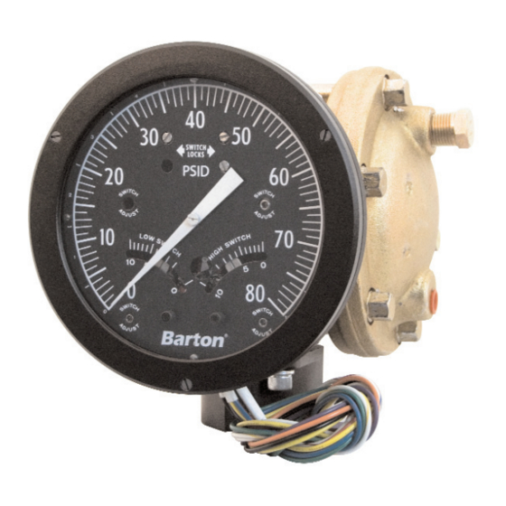
SeCTIoN 1 - INTRoDUCTIoN 1-1. General The Barton weatherproof Model 289A and the explosion-proof Model 291B are ® differential pressure indicating switches (Figure 1-1). The 289A has a NEMA-4 watertight die-cast aluminum case (finished with a weather-resistant black epoxy resin paint). The cover lens is secured in the bezel with an elastomer ring to reduce the possibility of accidental breakage. -
Page 4: Main Components
figure 1-2. Switches and adjustable controls 1-2. Main Components A. Indicating Switch B. Differential Pressure Unit (DPU) • 289A and 291B are actuated by a Barton Model 199 DPU ® For detailed information on the actuating DPU, see the Barton Model 199 DPU ®... -
Page 5: Indicating Switch
1-3. Indicating Switch (refer to Figures 1-3 and 2-1) Rotation of the DPU’s torque tube shaft is coupled through connecting linkage within the switch case to move the pointer across the scale plate. An actuating cam, directly connected to the torque tube shaft, rotates with the motion of the shaft. -
Page 6: Specifications
1-4. Specifications General: Actuating Unit (DPU) ....Barton Model 199 DPU ® Dial Size ........6 inches (152 mm) Temperature Limits (Ambient) ...40°F/°C to +180°F (+80°C) Indication Accuracy (SPDT) ..0-10” w.c. to 0-349” w.c. ± 1.0% F.S. (0-25 mbar to 0-867 mbar ± 1.0% F.S.) 0-350”... -
Page 7: Section 2 - Installation
SeCTIoN 2 - INSTallaTIoN 2-1. General The instrument should be inspected at time of unpacking to detect any damage that may have occurred during shipment. Note: The unit was checked for accuracy at the factory — do not change any of the settings during examination or accuracy will be affected. - Page 8 289A SWITCH AND RELAY 289A SWITCH ONLY HIGH N.O. N.C. N.C. N.O. HIGH WHITE/GRAY WHITE/VIOLET WHITE/BLUE WHITE/BLACK WHITE/BROWN WHITE/ORANGE N.C. N.C. N.O. N.O. BROWN ORANGE N.C. N.C. BLUE WHITE GRAY VIOLET N.O. N.O. BLACK BLACK 291B SWITCH AND RELAY 291B SWITCH ONLY HIGH N.O.
-
Page 9: Section 3 - Maintenance And Calibration
SeCTIoN 3 - MaINTeNaNCe aND CalIbRaTIoN 3-1. Required Tools (Toolkit Part No. 0288-1032B) Tool Purpose Pointer puller Pointer removal Small screwdriver Calibration adjustments Medium screwdriver Bezel removal/DPU bracket screws 1/8” Open-end wrench Calibration adjustments 1/8 Hex Allen wrench Switch setpoint adjustment 3-2. -
Page 10: Calibration Check
for explosionproof units, cover is unscrewed to gain access to the internal com- ponents. Note: On some units, a set screw must be loosened with a 1/8-in. allen wrench before the bezel can be removed. When re-installing cover, tighten cover securely and inspect lens for cracks or other defects that may affect the explosion- proof rating. -
Page 11: Indicator Calibration
Slide pointer puller along pointer until pin protruding from tip of screw in pointer puller is directly over movement shaft and arms of pointer puller are directly under pointer. Gently turn knurled head of screw clockwise, pushing pin against move- ment shaft and lifting pointer with arms. -
Page 12: Changing Switch Setpoint
Apply 0%, 25%, 50%, 75%, 100%, 75%, 50%, 25%, and 0% of full-scale differential pressure consecutively to instrument without overshoot. Lightly tap indicator to overcome friction. Pointer should accurately indicate each applied pressure. 10. Set stops to prevent pointer from striking snubbers on scale. Test setting by moving pointer from zero position to 50% position manually and then letting pointer return freely. - Page 13 Move index pointer (item C) to division 4. Start from bottom of switch index (0 on low, 10 on high). Tighten switch lock (item B) snug plus 1/4 turn. Do not over- tighten. This will place setpoint within ±2% of full scale. Out-of-Service (Disconnected from process Setpoint Adjustment lines or mounted on bench) Drain and vent housings.
-
Page 14: Complete Calibration
3-8. Complete Calibration Before performing complete calibration procedure, verify that instrument is out of calibration, by performing calibration check procedure (section 3-4), page 10. If instrument is out of calibration, before performing complete calibration proce- dure, remove bezel/lens and inspect switch mechanism to verify the following (see Figure 3-5) (See Warning on pg. -
Page 15: Preventative Maintenance
Calibration Procedure (continued) Tighten screw on crank to mid-slot position. Turn switch index pointer to “1” (index numbers refer to numbers on outer edge of scaleplate). Apply 10% differential pressure and adjust switch plate until switch actuates. Lock the two linkage screws. Rotate index pointer to “9.”... -
Page 16: Locking Drive Arm To Torque Tube
3-10. Locking Drive Arm to Torque Tube Refer to Model 199 DPU manual. For explosionproof units, refer to Figure 5-3, Model 291 Detail Drawing, pg. 28 (See Warning on pg. 9). Slip drive arm over torque tube shaft; clear end of torque-tube housing by approximately 0.030-in. - Page 17 Table 3-1. Troubleshooting Problem Possible Source Probable Cause Corrective Action Orifice installed backwards Replace orifice. Low or no Primary element or oversized Indication or DPU (refer to DPU Manual) Flow blocked upstream Clean out run or open from run valve. Loss of liquid in reference Refill reference leg.
- Page 18 Table 3-1. Troubleshooting (cont'd) Problem Possible Source Probable Cause Corrective Action High Loose linkage or movement Tighten or replace. Indicator, alarm switch indication Out of Calibration Calibrate. mechanism (cont'd) Flow pulsating M199 DPU – adjust Erratic Primary element indication dampening; All o hers –...
-
Page 19: Section 4 - Installation Drawings
SeCTIoN 4 - INSTallaTIoN/DIMeNSIoNal DRaWINGS figure 4-1. Model 289a outside Dimensions (Part 1 of 2) - Page 20 figure 4-2. Model 289a outside Dimensions (Part 2 of 2) Table 4-1. Model 289A Dimensions (as shown in Figure 4-1, pg. 19) PRESSURE PRESSURE DIM. A DIM. B DIM. C DIM. D HOUSING CONNECTION RATING INCHES INCHES INCHES INCHES MATERIAL PSI (MPa) (mm) (mm)
- Page 21 figure 4-3. Model 291b outside Dimensions (Part 1 of 2)
- Page 22 figure 4-4. Model 291b outside Dimensions (Part 2 of 2) Table 4-2. Model 291B Dimensions (as shown in Figure 4-3, pg. 21) PRESSURE PRESSURE DIM. A DIM. B HOUSING CONNECTION RATING INCHES INCHES MATERIAL PSI (MPa) (mm) (mm) BOTTOM 1/2 NPT 1/4 NPT 6-5/8 CAST ALUM.
-
Page 23: Section 5 - Parts Drawings/Parts Lists
Figure 5-1. Model 289A Assembly Drawing WARNING Use only spare parts identified in this manual. Cameron bears no legal respon- sibility for the performance of a product that has been serviced or repaired with parts that are not authorized by Cameron. - Page 24 Table 5-1. Model 289A Parts List ITEM DESCRIPTION PART NO. UNIT DIFFERENTIAL PRESSURE UNIT (NOT SHOWN) SEE DPU 199 MANUAL LOW ALARM, EXT. WIRING ASSY., 2.5’ LENGTH (NOT SHOWN): UNITS WITHOUT RELAY, SPDT 0288-0021B UNITS WITHOUT RELAY, DPDT S401-0018Z UNITS WITH RELAY, SPDT OR DPDT 0288-0008B HIGH ALARM, EXT.
- Page 25 Table 5-1. Model 289A Parts List (cont'd) ITEM DESCRIPTION PART NO. UNIT **13 POINTER ASSY.: WHITE 0288-0030B BLACK 0288-0031B BEZEL ASSY. (WITH PLASTIC LENS) 0277-0018B PLATE SCREW: LOW OR HIGH ALARM (SINGLE) 0317-0012C DUAL ALARM 0317-0012C SPRING WASHER: LOW OR HIGH ALARM (SINGLE) 0257-0019C DUAL ALARM 0257-0019C...
- Page 26 Table 5-1. Model 289A Parts List (cont'd) ITEM DESCRIPTION PART NO. UNIT CASE ASSEMBLY 0288-0038B SCREW, RETAINER 0181-0007C STOP, SNUBBER 0226-0028C **35 GASKET, BEZEL 0277-0026C RISER, MOVEMENT 0277-0035C BRACKET, STOP 0288-0028C BRACKET, TERMINAL BLOCK 0288-0029C SCREW, 6-32 X 3/8, SL., RD., HD. 0111-0015J SCREW, 4-40 X 3/16 SST, SL., FIL., HD.
- Page 27 Figure 5-2. Model 291B Assembly Drawing WARNING Use only spare parts identified in this manual. Cameron bears no legal respon- sibility for the performance of a product that has been serviced or repaired with parts that are not authorized by Cameron.
- Page 28 Figure 5-3. Model 291B Detail Drawing...
- Page 29 Table 5-2. Model 291B Parts List ITEM DESCRIPTION PART NO. UNIT DIFFERENTIAL PRESSURE UNIT (NOT SHOWN) SEE DPU 199 MANUAL HIGH EXTERNAL WIRING ASSY. (2.5’ Long): HIGH ALARM, SPDT (WITHOUT RELAY) S655-0056B HIGH ALARM, DPDT (WITHOUT RELAY) 290B-1090B HIGH ALARM (WITH RELAY) 290B-1084B LOW EXTERNAL WIRING ASSY.
- Page 30 Table 5-2. Model 291B Parts List (cont'd) ITEM DESCRIPTION PART NO. UNIT **12 POINTER ASSY.: WHITE 0288-0030B BLACK 0288-0031B PLATE SCREW: LOW OR HIGH ALARM (SINGLE) 0317-0012C DUAL ALARM 0317-0012C SPRING WASHER: LOW OR HIGH ALARM (SINGLE) 0257-0019C DUAL ALARM 0257-0019C SWITCH PLATE SPACER, HIGH ALARM (SINGLE) 0258-0007C...
- Page 31 Table 5-2. Model 291B Parts List (cont'd) ITEM DESCRIPTION PART NO. UNIT SCREW, 4-40 X 3/16, SST., SL, BINDING HD. 0117-0012J SCREW, 6-32 X 3/16 SST, SL. BINDING HD. 0117-0013J SCREW, 8-32 X 3/16, BIN. HD. 0117-0014J GROUND WIRE, GREEN IT10-1063B SCREW, SL, HEX, HD.
- Page 32 If any defect within this warranty appears, Buyer shall notify Cameron immediately. Cameron agrees to repair or furnish a replacement for, but not install, any product which within one (1) year from the date of shipment by Cameron shall, upon test and examination by Cameron, prove defective within the above warranty.
Need help?
Do you have a question about the Barton 289A and is the answer not in the manual?
Questions and answers