Table of Contents
Advertisement
Quick Links
Advertisement
Table of Contents

Subscribe to Our Youtube Channel
Related Manuals for CTC Union STE211


Summary of Contents for CTC Union STE211
- Page 1 User Manual STE211 Serial to Ethernet Interface Converter sales@ctcu.com...
- Page 2 8F, No. 60 Zhouzi St., Neihu, Taipei 114, Taiwan T +886-2-26591021 F +886-2-26590237 E sales@ctcu.com H www.ctcu.com 2022 CTC Union Technologies Co., LTD. All trademarks are the property of their respective owners. Technical information in this document is subject to change without notice.
-
Page 3: Table Of Contents
Table of Contents INTRODUCTION ....................... 4 OVERVIEW ....................... 5 PACKAGE CHECKLIST ....................5 PRODUCT SPECIFICATIONS ..................6 PRODUCT PANEL VIEWS ................... 8 ............................8 NTENNA ..........................9 ERIAL NTERFACE LED INDICATORS ....................10 WIRING ARCHITECTURE ..................11 CONFIGURATION ....................12 IP S ........................ -
Page 4: Introduction
Introduction STE211 Serial to Ethernet Interface Converter provides the ways of connecting serial devices to Ethernet. It is designed to operate serial ports through Ethernet (10/100Mbps) over TCP/IP network. As the data is transmitted via TCP/IP protocol, therefore data acquisition and controlling are available to go through Intranet and Internet. -
Page 5: Overview
Sensors to an IP-based Ethernet host, and makes it possible to access Serial interface devices anywhere and anytime via your software. STE211 provides TCP Server Mode, TCP Client Mode, and UDP Mode for selection. It also supports manual configuration via web browser and support various protocols including HTTP, DHCP, ICMP, and ARP. -
Page 6: Product Specifications
Product Specifications System CPU: MT7688AN MIPS CPU, 580 MHz RAM: 128M Bytes DDR2 RAM ROM: 32M Bytes Flash ROM OS: OpenWrt Linux OS Ethernet Port Type: RJ-45 Connector Speed: 10 /100 M bps (Auto Detecting) ... - Page 7 Mechanical and Environment Operating Temperature: -20°C~70°C Storage Temperature: -25°C~80°C Dimensions: 110mm (W) * 90mm (D) * 26 mm (H) Weight : 110 ± 5gm Housing: plastic Other Features LED Indicators: SYS, WiFi, RX, TX, LAN ...
-
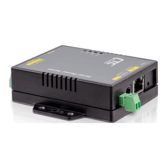
Page 8: Product Panel Views
Product Panel Views Antenna Side DC-IN Power Outlet Ethernet (DC Jack) LAN port Reset Push Button DC-IN Power Outlet (Terminal Block) Ethernet Port The connector for network is the usual RJ45. Simply connect it to your network switch or Hub. When the connection is made, the green color LED of Ethernet port will blink. -
Page 9: Serial Interface Side
DC Power outlet Reset Button (1) Press reset key after 5 seconds until SYS LED flash then release the key will reset network default IP and gateway IP back to default. The other parameters keep same as last confirmation. (2) Press reset key after 5 seconds until both SYS LED and WiFi LED flash then release the key will make all parameters back to factory default. -
Page 10: Led Indicators
LED Indicators SYS (Green): Power indicator. When the power is on, the LED will be lit and blink per second. WiFi (Red): (WiFi is only for WiFi models.) WiFi indicator. When the WiFi is working, this LED blinks. Tx (Green): Data sending indicator. -
Page 11: Wiring Architecture
Wiring Architecture 1. RS-232 2. RS-422/RS-485 When you complete the steps mentioned above, the LED indicators will be lit. This means that the converter is connected and installed correctly. To proceed with the parameters setup, please use a web browser (IE or Chrome) to configure the detailed settings. -
Page 12: Configuration
Configuration When setting up your converter for the first time, the first thing you should do is to configure the IP address. You can use IP Device Search tool to find the IP or simply use the default IP to login to the device. The following topics are covered in this chapter: ... - Page 13 5. Click on “Find” button. It will scan the network and show up the IP of the converter. 6. Click “Setup” button will pop up a window. You may change Name, Description, IP, Netmask of device. Click “Setup” to save setup. The device’s IP must be same subnet with host PC/NB enable to use web browser open configuration page.
- Page 14 8. You can also use the default IP address (10.1.1.1) to login to the configuration webpage with the default Username: admin and Password: admin. 9. When you successfully login to the device, the following main screen will pop up.
-
Page 15: Web Browser Configuration
Web Browser Configuration There are 4 setup pages as “System”, “Network”, “Serial” and “Over TCP/IP”. System Setup 1. System: where you can change Password, set up Auto Reset time and modify Device Name, Description of device. 2. Appearance of Wireless and Ethernet setup. - Page 16 3. HTTP & NTP: Enable / Disable HTTP or NTP function; Set up NTP server and Time Zone. Firmware update: If necessary, click “Browse” to open file manager. Then, select the file with specified version and click “open” button. When the selected file name appears on the input column, click “Update” button. 5.
-
Page 17: Network Setup
Network Setup 1. Ethernet section: Select “STATIC” or “DHCP” to assign IP address. - Page 18 2. Gateway and DNS: To check with MIS for right IP address. 3. TCP Keep Alive: Set up TCP keepalive time, interval and probes. 4. Up to now, Setup is successfully configured. Please click “Save” for this page temporarily and go to other pages for configuration or click “Save and Restart” to run this Device with new settings.
-
Page 19: Serial Port Setup
Serial Port Setup Please correctly input each parameter to match with the remote terminal unit. Baud Rate: 300 bps to 921.6K bps Parity: None, Even, Odd Data Bits: 5, 6, 7, 8 Stop Bits: 1, 2 Flow Control: None, XON/XOFF RxDelay(ms) TxDelay(ms) Up to now, Setup is successfully configured. -
Page 20: Over Tcp/Ip Setup
Over TCP/IP Setup 1. There are 3 TCP modes available for selection: TCP Server/ TCP Client/ UDP. 2. TCP Server: Configure TCP server port number and message time out period. At this mode, this device will wait for client connection. - Page 21 3. TCP Client: Allow to configure 4 remote destination host IP addresses and port numbers. At TCP client mode, this device establishes a connection with remote host and sending data to remote host actively. 4. UDP: Allow to configure 4 remote destination host IP addresses and port numbers. At UDP mode, this device establishes a connection with the remote host and sends data to the remote host actively.
- Page 22 5. Up to now, Setup is successfully configured. Please click “Save” and go to other pages for configuration or click “Save and Restart” to run new configuration. 6. After configuring all parameters, click “Save and Restart” to reboot system.
-
Page 23: Reset Push Button
Reset Push Button (1) Press reset key for 5 seconds or longer until SYS LED flash. Then, releasing the reset key will reset network default IP and gateway IP back to default settings. The other parameters remain the same as the last confirmation. (2) Press reset key for 5 seconds or longer until both SYS LED and WiFi LED flash. - Page 24 Date Version 2022/9/30 V1.0 (202101a) Preliminary version (outsourced)
Need help?
Do you have a question about the STE211 and is the answer not in the manual?
Questions and answers