Advertisement
Quick Links
Flow Sensor SFAB
Operating instructions
Original: de
Note
Installation and commissioning may only be performed in accordance with thess
instructions by technicians with appropriate qualifications.
Note
The product is suitable for use only for industrial purposes.
In residential areas, measures for radio interference suppression may be
necessary. It is not suitable for commercial invoicing, such as for measurement
of air consumption in public utilities.
1
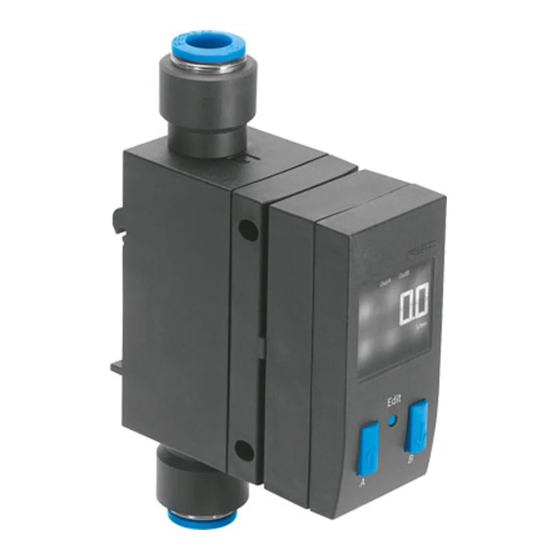
Product description
1.1 Overview
9
8
7
6
1
Supply port 1
è Marking on the product
2
Display
3
B button
4
Edit button
5
A button
Fig. 1
Festo AG & Co. KG
Postfach
D−73726 Esslingen
++49/711/347−0
www.festo.com
743 851
0811NH
1
2
3
4
5
6
Plug for electrical
connection (M12)
7
Supply port 2
è Marking on the product
8
Hole for fitting the plate
9
Fastening slide for hat rail fitting
and wall fitting (rear)
1.2 Characteristics
Order code Design
Feature
Basic version
SFAB
Flow measuring range
g
g
−10
−50
−200
−600
−1000
Flow input
U
Type of mounting
yp
g
−H
−W
Pneumatic connection
Q6
Q8
Q10
T14
T516
T38
Electrical output
p
−2SA
−2SV
Electrical connection
−M12
Additional function at
−D
1)
Electrical accessories
−2.5S
−5S
−2.5A
−5A
1) Included in the scope of delivery.
Fig. 2
2
Function and application
The SFAB is designed to monitor changes in flow and air consumption for suitable
media in piping systems or end devices in industry; suitable media è chapter 11
Technical specifications. Measurement is carried out by means of a thermal
procedure. The amount of heat, which is drawn from a heated surface of the
sensor by the medium flowing through it, is calculated here. Through the amount
of heat removed, the flow or accumulated air consumption is determined and
shown on the display. The connection to higher−level systems is made via 2 binary
outputs (Out A/B) and one analogue output (Out C). Switching points can be set
for both binary outputs. For flow measurement, switching points are possible for
both binary outputs, and for accumulated air consumption meaurement a
consumption switch impulse for output A (Out A). The combination of accumulated
air consumption measurement (Out A) and flow measurement (Out B) is possible.
The flow value is output via the analogue output. Up to a flow range of 200 l/min,
an integrated flow actuator can be optionally ordered. This permits setting the flow
with the precision described in chapter 11, Technical specifications.
3
Conditions for the safe use of the product
Warning
Depending on the functioning of the machine/system, manipulation of signal
states may cause serious personal injury.
· Note that if the switching status of the outputs is modified in Edit mode,
the new status will be effective immediately.
· Activate the password protection (security code) in order to prevent the
unintentional change by unauthorised third parties è chapter 5.4, section
Security code.
Warning
Use of the product in combination with prohibited media can result in personal
injury.
· Do not use the product in conjunction with inflammable gases, corrosive
gases, oxygen etc. The product is intended only for measuring the flow of
media, which are listed as suitable in the chapter 11 Technical specifications.
Important
Condensation water, oil mist, foreign matter and other dirt in the compressed air
can damage the product and cause incorrect measurements and functional
disorders.
· Make sure that the specified air quality class is maintained for the operating
medium è chapter 11 Technical specifications.
Flow sensor
Max. 10 l/min
Max. 50 l/min
Max. 200 l/min
Max. 600 l/min
Max. 1000 l/min
Unidirectional
Via DIN H−rail
With wall fastening
Push−in connector 6 mm
Push−in connector 8 mm
Push−in connector 10 mm
Push−in connector for 1/4"
Push−in connector for 5/16"
Push−in connector for 3/8"
2x PNP or NPN, 1 analogue output 4
20 mA
2x PNP or NPN, 1 analogue output 0
10 V
Plug M12x1, 5−pin, A−coded
Final control element
Connecting cable, straight socket, cable 2.5 m
Connecting cable, straight socket, cable 5 m
Connecting cable, angled socket, cable 2.5 m
Connecting cable, angled socket, cable 5 m
Advertisement

Related Manuals for Festo SFAB-10U


Summary of Contents for Festo SFAB-10U
- Page 1 Max. 10 l/min −50 Max. 50 l/min −200 Max. 200 l/min −600 Max. 600 l/min −1000 Max. 1000 l/min Festo AG & Co. KG Flow input Unidirectional Postfach Type of mounting −H Via DIN H−rail D−73726 Esslingen −W With wall fastening ++49/711/347−0...
- Page 2 4.3 Electrical connection Note Warning Improper handling can result in malfunctions. · Make sure that the following specifications are always observed: Use only power units which guarantee reliable electrical isolation of the operating voltage as per IEC/DIN EN 60204−1. · Compare the maximum values specified in these operating instructions with Observe also the general requirements for PELV power circuits as per your actual application (e.g.
- Page 3 Preparing commissioning Consumption switch impulse [CI] with accumulated air consumption In the base state, the product is in the RUN mode. The current measurement measurement values are displayed. The base state can be reached from other modes by: Setting NO (normally open closer) Setting NC (normally closed opener) pressing Edit button for 3 seconds or passage of a monitoring time, timeout...
- Page 4 The following settings are displayed for OUT A: With flow measurement [FLW]: the switching function (threshold value or window comparator) switching point [SP], switching points [SP.Lo] and [SP.Hi] hysteresis [Hy] switching element function [no/nc] (closer/opener) minimum flow value [F.Lo] (Flow Low). In order to delete the minimum value, press the EDIT button briefly.
- Page 5 The EDIT mode enables the following settings: b) Setting switching function for air consumption measurement switching mode for Out A (air consumption [ConS] or flow [FLW] ) The SFAB is in the EDIT mode and [Out A] flashes, è Start EDIT mode section. switching function (threshold−value or window comparator for Out A and Out B) Press the Edit button to confirm the selection.
-
Page 6: Teach Mode
a) Setting standard conditions The air mass stream measured and output from the SFAB refers to standard Note conditions. The SFAB is calibrated at the factory to the physical standard A high filter time constant and high smoothing can result in a response time of conditions in accordance with DIN 1343. -
Page 7: Operation
Select the appropriate accessories from our catalogue. · Avoid high cycle frequencies with large pressure amplitudes. Otherwise, the è www.festo.com/catalogue/SFAB admissible limit temperatures of the used materials will be exceeded. The air mass stream displayed by the SFAB refers to the standard conditions that were set under Options in the special menu. -
Page 8: 11 Technical Specifications
Technical specifications SFAB −10U −50U −200U −600U −1000U SFAB −10U −50U −200U −600U −1000U General information Mechanical components Certification C tick Temperature dependency of the throttle setting ±FS CE symbol (è conformity declaration) to EU EMC directive 50 °C) Note on materials RoHS−compliant Assembly position as desired...