Sign In
Upload
Manuals
Brands
Woodward Manuals
Relays
MRI3
Woodward MRI3 Manuals
Manuals and User Guides for Woodward MRI3. We have
1
Woodward MRI3 manual available for free PDF download: Manual
Woodward MRI3 Manual (68 pages)
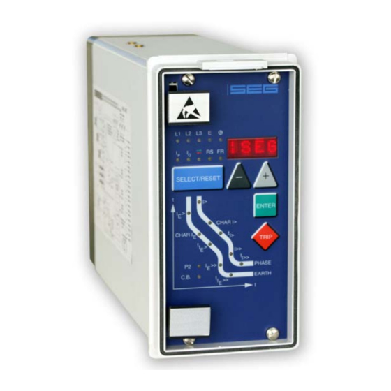
Digital multifunctional relay for overcurrent protection
Brand:
Woodward
| Category:
Relays
| Size: 1 MB
Table of Contents
Table of Contents
3
1 Introduction and Application
5
2 Features and Characteristics
6
3 Design
7
Connections
7
Analog Input Circuits
9
Output Relays
9
Blocking Input
10
External Reset Input
10
Relay Output Contacts
10
Fault Recorder
11
Parameter Settings (See Chapter 5)
12
Leds
17
4 Working Principle
18
Analog Circuits
18
Digital Circuits
18
Directional Feature
19
Reversal in Direction During the Activation Phase
19
Earth Fault Protection
23
Generator Stator Earth Fault Protection
23
System Earth Fault Protection
23
Earth-Fault Directional Feature (ER/XR-Relay Type)
24
Determining Earth Short-Circuit Fault Direction (SR/YR-Relay Type)
26
Directly - Earthed System
26
Resistance - Earthed System
27
Connection Possibilities of the Voltage Transformers for SR Relay Types
28
Demand Imposed on the Main Current Transformers
28
5 Operation and Settings
29
Display
29
Setting Procedure
30
System Parameter
31
Display of Measuring Values as Primary Quantities
31
Prim Phase)
31
Display of Earth Current as Primary Quantity
31
Prim Earth)
31
Voltage Transformer Connection for Residual Voltage Measuring (3Pha/E-N/1:1)
31
Display of Residual Voltage U as Primary Quantity
31
Prim /U Sec )
31
Nominal Frequency
31
Display of the Activation Storage (FLSH/NOFL)
32
Parameter Switch/External Triggering of the Fault Recorder
32
Parameter Protection
33
Pickup Current for Phase Overcurrent Element (I>)
33
Time Current Characteristics for Phase Overcurrent Element (CHAR I>)
33
Trip Delay or Time Factor for Phase Overcurrent Element (Ti>)
33
Reset Setting for All Tripping Characteristics in the Phase Current Path
34
Current Setting for High Set Element (I>>)
34
Trip Delay for High Set Element (Ti>>)
34
Relay Characteristic Angle RCA
34
Pickup Value for Residual Voltage UE (ER/XR-Relay Type)
34
Pickup Current for Earth Fault Element (IE>)
34
WARN/TRIP Changeover (All Earth Fault-Relay Type)
35
Time Current Characteristics for Earth Fault Element (CHAR I Type)
35
E )
35
Trip Delay or Time Multiplier for Earth Fault Element (T IE>> )
35
Reset Mode for Inverse Time Tripping in Earth Current Path
35
Current Setting for High Set Element of Earth Fault Supervision (I )
35
Current Setting for High Set Element of Earth Fault Supervision (I Trip Delay for High Set Element of Earth Fault Supervision (T IE>> )
35
COS/SIN Measurement (ER/XR-Relay Type)
35
SOLI/RESI Changeover (SR/YR-Relay Type)
36
Block/Trip - Time
36
Circuit Breaker Failure Protection Tcbfp
36
Adjustment of the Slave Address
36
Setting of Baud-Rate (Applies for Modbus Protocol Only)
36
Setting of Parity (Applies for Modbus Protocol Only)
36
Fault Recorder
37
Adjustment of the Fault Recorder
37
Number of the Fault Recordings
37
Adjustment of Trigger Occurrences
37
Pre-Trigger Time (Tpre)
37
Adjustment of the Clock
38
Additional Functions
38
Blocking the Protection Functions and Assignment of the Output Relays
38
Setting Value Calculation
40
Definite Time Overcurrent Element
40
Inverse Time Overcurrent Element
41
Indication of Measuring and Fault Values
41
Indication of Measuring Values
41
Units of the Measuring Values Displayed
42
Indication of Fault Data
44
Fault Memory
44
Reset
45
Erasure of Fault Storage
45
6 Relay Testing and Commissioning
46
Power-On
46
Testing the Output Relays and Leds
46
Checking the Set Values
46
Secondary Injection Test
47
Test Equipment
47
Example of Test Circuit for MRI3 Relays Without Directional Feature
47
Checking the Input Circuits and Measured Values
48
Checking the Operating and Resetting Values of the Relay
48
Checking the Relay Operating Time
48
Checking the High Set Element of the Relay
48
Example of a Test Circuit for MRI3 Relay with Directional Feature
49
Test Circuit Earth Fault Directional Feature
51
Checking the External Blocking and Reset Functions
52
Testing the External Blocking with Block/Trip Function
52
Test of the CB Failure Protection
52
Primary Injection Test
53
Maintenance
53
7 Technical Data
54
Measuring Input Circuits
54
Common Data
54
Setting Ranges and Steps
55
Time Overcurrent Protection (I-Type)
55
Earth Fault Protection (SR/YR-Type)
55
Earth Fault Protection (E/X-Type)
55
Earth Fault Protection (ER/XR-Type)
56
Block/Trip - Time
56
Switch Failure Protection
56
Interface Parameter
56
Parameter for the Fault Recorder
56
Inverse Time Overcurrent Protection Relay
57
Direction Unit for Phase Overcurrent Relay
58
Determination of Earth Fault Direction (Mrl3-ER/XR)
58
Determination of Earth Fault Direction (Mrl3-SR/YR)
58
Inverse Time Characteristics
59
Output Contacts
62
8 Order Form
63
Advertisement
Advertisement
Related Products
Woodward highprotec MRI4
Woodward MRI3-ITE
Woodward MRI3-ITER
Woodward MRIK3-C
Woodward MRIK3
Woodward MRG3-IUO
Woodward MRG3-IE-M
Woodward MRR1
Woodward MRG3-IER-M
Woodward MRG3-I-M
Woodward Categories
Controller
Control Unit
Relays
Control Systems
Industrial Equipment
More Woodward Manuals
Login
Sign In
OR
Sign in with Facebook
Sign in with Google
Upload manual
Upload from disk
Upload from URL