Table of Contents
Advertisement
Quick Links
Advertisement
Table of Contents

Related Manuals for Pulsar blackbox 134


Summary of Contents for Pulsar blackbox 134
- Page 1 134 NSTRUCTION ANUAL...
- Page 3 ARRANTY AND IABILITY Pulsar Process Measurement Limited guarantee for a period of 2 years from the date of delivery that it will either exchange or repair any part of this product returned to Pulsar Process Measurement Limited if it is found to be defective in material or workmanship, subject to the defect not being due to unfair wear and tear, misuse, modification or alteration, accident, misapplication or negligence.
-
Page 5: Table Of Contents
Contents Chapter 1 Start Here… ..............................1 About this Manual ..............................1 About the blackbox range ............................2 Functional Description ..............................3 Product Specification ..............................4 EU Declaration of Conformity ..........................6 Chapter 2 Installation ..............................7 Power Supply Requirements ............................7 Location ..................................7 Dimensions..................................8 Standard Enclosure ............................8 Large Enclosure (optional) .......................... - Page 6 Volume Menu ..............................42 Display Menu ..............................43 Compensation Menu ............................43 Stability Menu ..............................44 Echo Processing Menu........................... 44 System Menu ..............................45 Test Menu ................................ 46 Parameter Listing ..............................47 Application Parameters ............................47 Operation ................................47 Dimensions ..............................48 Device Set Up..............................
- Page 7 Error Checking ..............................84 Message Timings ..............................86 Mode of Transmission ........................... 86 Wait Period ..............................86 Latency ................................87 Message Transmission Time ........................87 Modbus Functions ..............................88 Function 1: Read Output Status ..........................88 Example: Query: reading relay 2 to 4 ......................88 Function 2: Read Input Status ..........................
- Page 8 Chapter 9 Disposal ..............................105 Parameter Record ................................107...
-
Page 9: Chapter 1 Start Here
Chapter 1 Start Here… Congratulations on your purchase of a Pulsar blackbox 134 Level Comms (Modbus) System. This quality system has been developed over many years and represents the latest in high technology ultrasonic level measurement and control. It has been designed to give you years of trouble free performance, and a few minutes spent reading this operating manual will ensure that your installation is as simple as possible. -
Page 10: About The Blackbox Range
About the range The Pulsar blackbox is a non-contact Level Control System. It has been designed to provide a new concept in low cost maintenance-free fit and forget level measurement without any compromise on performance. The blackbox is ideally suited to applications where level monitoring, reporting, control or logging is required, with or without the need for a local display. -
Page 11: Functional Description
The blackbox utilises the unique DATEM software (Digital Adaptive Tracking of Echo Movement). This is a unique digital mapping technique developed especially for Pulsar’s range of ultrasonic level and control systems. It gives the system edge when identifying the “true target level” in the face of competing echoes from pipes, pumps or other obstructions. -
Page 12: Product Specification
Transducer cable extensions 2-core screened (2 conductor 20AWG screened) Nominal separation 1000 m (3,280 ft.). 500m (1,640 ft.) for dBR16. For greater distances consult Pulsar Environmental IP Rating IP66 with display IP67 Without display Max. & min. temperature (electronics) -20 ºC to +50 ºC (-4ºF to 120ºF) - Page 13 50 mA at 230 VAC (fitted as standard) 100 mA at 115 VAC Remote Communicator Power supplied via BlackBox RS232 Power Supply interface. Pulsar Process Measurement Limited operates a policy of constant development and improvement and reserve the right to amend technical details as necessary. Page...
-
Page 14: Eu Declaration Of Conformity
EU Declaration of Conformity Page... -
Page 15: Chapter 2 Installation
Chapter 2 Installation Power Supply Requirements The BlackBox can operate from AC supply or from a DC battery. The AC is 115V +5%/-10% 50/60Hz or 230V +5%/-10% 50/60Hz, depending on the position of the selector switch. The DC is 10-28V. In all cases the BlackBox will typically consume 5W of power, with a maximum of 10W. -
Page 16: Dimensions
When choosing a location to mount the enclosure, bear in mind the following: • Ensure that the blackbox is installed in a “Safe”, non-hazardous, area. • Easy access to the enclosure is maintained. • The mounting surface is vibration-free. • The ambient temperature is between -20ºC and 50ºC (-4ºF and 120ºF). - Page 17 The blackbox should be mounted by drilling four holes suitable for size 8 screws (length and type to suit your application) And fix all four screws by removing the top cover to access the pre-moulded mounting holes which are located in the base of the enclosure under the lid retaining screws. The full dimensions of the enclosure are as shown below.
-
Page 18: Large Enclosure (Optional)
Large Enclosure (optional) The dimensions of the mounting holes are as shown below. Page... - Page 19 The full dimensions of the enclosure are as shown below. Cable Entry There are 5 x 20mm (0.79") cable glands, suitable for 6 – 12mm (0.24" – 0.63") cables, fitted to the base of the fitted to the base of the BlackBox enclosure. Page...
-
Page 20: Terminal Connection Details
Terminal Connection Details The terminal strip is as detailed below. There is also a wiring diagram attached to the board directly underneath the terminal strip. Page... -
Page 21: Power
Terminal Connections Power The blackbox can operate from mains AC and automatically from a DC power source or battery backup, in the event of power failure, or can be operated permanently from DC or batteries. Transducer The transducer should be installed, and connected, in accordance with the installation instructions contained in the Transducer User Guide. -
Page 22: Relay Outputs
For EEx m (Zone 1) applications a transducer certified to FM Class I Div 1 Group A, B, C & D, ClassII Div 1 Group E, F & G, Class III is used, and must be supplied via a 1500A breaking fuse, which is fitted as standard to the blackbox level controller. -
Page 23: Rs485 Serial Interface
(slaves) to a Modbus (master) device. Connecting the RS 485 The blackbox 134 is designed for 2 wire RS 485, however, if your controller has a 4 wire system then link as follows: RX+ and TX+ are to be linked and connected to RS 485 positive and RX- and TX- are to be linked and connected to RS 485 negative. -
Page 24: Voltage Selector And Fuse Location
Voltage Selector and Fuse Location The voltage selector switch and AC mains power fuse is located, on the bottom board to the left and above of the power input terminals, as previously illustrated in the Terminal Connections Detail drawing. Important Information Before applying AC power (mains), make sure you have correctly selected the voltage selector switch which is located to the left and above of the mains supply input terminals, as illustrated in the... -
Page 25: Preparation For Operation
There are no user serviceable parts inside your blackbox, except the mains power fuse. If you experience any problems with the equipment, then please contact Pulsar Process Measurement for advice. To clean the equipment, wipe with a damp cloth. Do not use any solvents on the enclosure or transducer. - Page 26 This page left blank intentionally Page...
-
Page 27: Chapter 3 How To Use Your Blackbox Level System
PC Handheld Programmer (Standard) Your blackbox 134 comes complete with the PC Handheld Programmer software, contained on CD. Insert the CD into the CD drive of the PC intended to be used to carry out the programming of the blackbox and install the software, following the on screen instructions. -
Page 28: Handheld Communicator (Optional)
‘right click’ on the PC Handheld Programmer keypad and a ‘pop up’ menu will appear allowing you to select the appropriate communications port. Handheld Communicator (Optional) The optional Handheld communicator can be used to programme any number of blackbox units and works in a similar way to the PC Software. Connect the Handheld Communicator, with the cable supplied, to the RS232 interface via the RJ11 connector located on the terminal connector, inside the blackbox enclosure. -
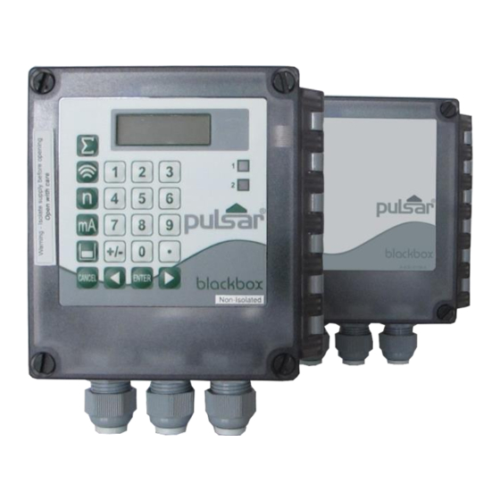
Page 29: On Board Integral Keypad And Display (Optional)
On board integral Keypad and Display (Optional) When fitted, the blackbox can be programmed directly via the integral keypad. Page... -
Page 30: Operating The Controls
Operating the Controls Display The display in all cases is identical, the only difference being is that both the PC Programming Software (standard) and the Hand Held Calibrator (optional) need to be connected to the blackbox via the RS232 interface, whereas the On-board keypad and display (optional) are permanently connected to the blackbox provides information on the current mode of operation. -
Page 31: Keypad
Run Mode. In program mode, they have different functions, the functions are shown below. Run Mode Program Mode Not used with blackbox 134. Not used with blackbox 134. Not used with blackbox Displays echo confidence, echo strength, H.A.L.L., average... - Page 32 Menu Keys The menu keys are used to navigate around the built in menu system and have the following functions: Menu Key Function 1) Arrow keys for moving left and right around the menu system. 2) Used in test mode to simulate the level moving up and down.
-
Page 33: Run Mode
There are two main operating modes for your blackbox, Run Mode and Program Mode. There is also a Test Mode, used for checking the set-up. All modes are now described. Run Mode This mode is used once the blackbox has been set up in program mode. It is also the default mode that the unit reverts to when it resumes operation after a power failure. -
Page 34: Led's
LED’s There are two LED’s which can be seen through the lid, of the blackbox enclosure, which will indicate the operational status of the unit while in RUN mode, as follows: blackbox without on board display (standard). LED 1 LED 2 Run Mode Green No power to unit... -
Page 35: How To Access Program Mode
How to Access Program Mode To enter program mode, you simply enter the passcode, via the keypad on the PC Programming Software (standard), Hand Held Calibrator (optional) or integral keypad (optional), followed by the ENTER key. The default passcode is 1997, so you would press the following: 1 9 9 7 Note There is a time-out period of 15 minutes when in program mode,... - Page 36 Once you have reached the relevant section, scroll through the parameters, and enter the necessary information. To enter the information, use the numeric keys and press ENTER and you will see the message “Saved!”, if you press CANCEL, then no change will be made, and the message “Unchanged!!” will be displayed.
-
Page 37: Test Mode
Test Mode Test mode is used to simulate the application and confirm that all parameters and relay setpoints have been entered as expected. During simulation, there is a choice of whether the relays will physically change state (hard simulation) or not (soft simulation), the LED’s will always change state to indicate that the relay setpoints have been activated. -
Page 38: Led's
The RS232 serial interface is used to program the blackbox, and communicate between the blackbox and a PC using the optional blackbox PC and other associated Pulsar software packages, to obtain information such as data logging and view echo traces upload, download and save parameter files. -
Page 39: Parameter Defaults
Parameter Defaults Factory Defaults Factory Defaults When first installing the blackbox, or subsequently moving or using the unit on a new application, before proceeding to program the unit for its intended application it is recommended that you ensure that all parameters are at their default values by completing a Factory Defaults P930, as described in Chapter 5 Parameter Guide. - Page 40 This page left blank intentionally Page...
-
Page 41: Chapter 4 Programming Guide
Chapter 4 Programming Guide Level Example 1 Level Measurement empty distance (P105), 3.5m 100%, span (P106), 3.2m high alarm on (P213), 2.5m high alarm off (P214), 2.4m low alarm off (P224), 0.6m low alarm on (P223), 0.5m 0% , empty level In this example, the blackbox and dB6 is being used to monitor a moving level within a vessel. - Page 42 To program the blackbox for this Example, proceed as follows. Access the Program Mode Key in the passcode 1997 and press ENTER Using the menu system access the parameters, as detailed below, and select the relevant options and ENTER. Top Level Selected Parameter Detail Sub Menu...
-
Page 43: Example 2 Alternating Control (Pump Down)
Example 2 Alternating Control (pump down) A sump is typically used to temporarily hold water or effluent, and when the level reaches a specific point, the sump is pumped down, with the fluid being transferred to another process. empty distance (P105), 5.0m 100%, span (P106), 4.7m pump 2 on (P 223), 1.4m pump 1 on (P 213), 1.0m... - Page 44 To program the blackbox for this Example, proceed as follows. Access the Program Mode Key in the passcode 1997 and press ENTER Using the menu system access the parameters, as detailed below, and select the relevant options and ENTER. Top Level Parameter Selected Sub Menu...
-
Page 45: Volume (Optional)
Volume (Optional) Example 3 Volume Application Only available on blackbox 134D, fitted with optional LCD display and integral keypad. A cylindrical tank with a diameter of 2m and a flat base that is typically used to temporarily hold liquid, and you wish to know the volume of liquid. You also require a high and low alarm. - Page 46 To program the blackbox for this Example, proceed as follows. Access the Program Mode Key in the passcode 1997 and press ENTER Using the menu system access the parameters, as detailed below, and select the relevant options and ENTER. Parameter Detail Selected Value Level Menu...
-
Page 47: Chapter 5 Parameter Guide
Chapter 5 Parameter Guide This chapter describes all of the parameters contained in your blackbox. Menu System Diagrams Shown below is a set of charts to show you how all the various parts can be found using the menu system. Top Level Menu Volume Application... -
Page 48: Application Menu
Application Menu Device Remote Operation Distances Setup Alarm Time P104 P100 P130 P985 P995 Measurement Mode Device Mode Tel. No 1 Interval Units P101 P131 P986 Tel. P996 P105 Transducer Protocol No 2 SMS Start Empty Level P997 P102 P132 P987 Tel. -
Page 49: Relays Menu
Relays Menu Relay 1 Relay 2 P210 R1 Type P220 R2 Type P221 R2 Function P211 R1 Function P212 R1 ID P222 R2 ID P213 R1 Set 1 P223 R2 Set 1 P214 R1 Set 2 P224 R2 Set 2 P217 R1 Closures P227 R2 Closures P218 R1 Failsafe... -
Page 50: Volume Menu
Volume Menu Only available on blackbox 134D, fitted with optional LCD display and integral keypad. Conversion Breakpoints Tables P600 P610 P696 Vessel Shape Level Bkpt. 1 Reset Bkpts. P611 P601 Vol. Bkpt. 1 As Required Vol. Dimension 1 P612, 614, 616, 618, P602 620, 622, 624, 626, As Required... -
Page 51: Display Menu
Display Menu Options Fail Safe P800 P808 Disp. Unit Fail Mode P801 P809 Decimal Fail Time Places P802 Disp. Offset P804 Disp. Conversion Compensation Menu Offset Temperature P851 P852 Measurement Temperature Offset Source P854 Fixed Temperature Page... -
Page 52: Stability Menu
Stability Menu Damping Filters P870 P881 Fill Damping Fixed Distance P871 P882 Empty Damping Process Filter Echo Processing Menu Transducer (Xdr.) Status P900 Xdr. 1 Status P901 Echo Confidence P902 Echo Strength P903 Average Noise P904 Peak Noise P905 Sensitivity P906 Side Clearance Page... -
Page 53: System Menu
System Menu Date System Daylight Passcode & Info Saving Time P926 P921 P931 P970 Software Enable Date Revision Code Enable P932 P971 P927 P922 Time Hardware Passcode Difference Revision P933 Date P972 P928 Format Serial Start Time Number P973 P929 Start Day Site Ident. -
Page 54: Test Menu
Test Menu Simulation Hardware P990 P980 Self Test Simulate P981 P991 Increment Hard Test P982 P993 Rate Relay Test P994 Transducer Test Page... -
Page 55: Parameter Listing
Transducer is a mmWave radar. Range 0.077 to 16m Important Information *dBR16 is available as an option in P101 when used with BlackBox firmware 2.1.0 and greater. For older versions of firmware, please consult your Pulsar distributor for assistance. Page... -
Page 56: Dimensions
P102 Material This parameter should be set to monitor the type of material being monitored. Option Description 0 = Liquid Use for liquids and flat solid materials 1 = Solid Solid material that is heaped or at an angle (Default) Use for applications within a closed tank or where a secondary echo response may become focused to 2 = Closed tank... - Page 57 P106 Span This parameter should be set to the maximum distance from the Empty Level (P105) to the maximum material level. It is automatically set to be equal to the Empty Level (P105) less the Near Blanking distance (P107), when you set the empty level.
-
Page 58: Device Set Up
Device Set Up The following parameters are used to configure the RS485 Communications. P130 Device Mode This parameter it used to determine whether the blackbox is a master or a slave device. Option Description 0 = Off (Default) Communications is switched OFF blackbox is set as a Slave unit 1 = Slave blackbox is set as the Master unit... -
Page 59: Remote Alarm
When a Modem is connected to the blackbox, via the RS232 port, (Consult Pulsar or your local distributor for further details), the following parameters are used to set up the blackbox so that when the level reaches a specific alarm point, as determined by the setting of the relay(s) the unit will dial and connect to a remote telephone number to provide details of the event. - Page 60 This option initiates a connection to a remote modem/computer which will then allow remote communication with the unit. Please 1 = Ring consult Pulsar or your local distributor for further details. This option initiates a predetermined message which is sent to the remote...
-
Page 61: Sms Time
SMS Time The following parameters determine when and how often a SMS message is to be sent. P995 SMS Interval This parameter determines how often a SMS message will be sent. If the time interval is set at ‘0.00 mins.’ then a SMS message will only be sent when an alarm condition occurs, when the time interval is set to anything other than zero then a SMS message will be sent at the relevant interval detailing the current level and/or any alarm condition present at that time. -
Page 62: Relay Parameters
Relay Parameters All relay related parameters are prefixed with a 2**. The second digit of the three figure parameter number denotes the relay number as follows: 21* parameters for Relay 1 22* parameters for Relay 2 The third digit selects specific parameters for the setting up of the relays, which can be selected individually and results in the following parameter numbers for each relay. -
Page 63: Alarms
Alarms P210, P220 =1 (Alarm) The second parameter for each relay determines the function of the alarm. P211, P221 - Relay Function This parameter defines what function the alarm will respond to as follows. Option Description 0= Off (Default) Relay will not operate. Alarm is based on the level in the vessel, and the type of level alarm (P212, 222) and two setpoints must be set (P213, 223 &... - Page 64 When P211, P221 = 1 (Level) or 2 (Temperature) This parameter defines which alarm type, the relay should respond to, as follows: Alarm ID Description Setpoints Relay goes “ON” when P213, 223 is ON the value reaches the ON Setpoint; P214, 224 setpoint and goes “OFF”...
-
Page 65: Control
Alarm ID Description Setpoints Relay Setpoints P213, 223 and Relay goes “ON” if P214, 224 can be value is outside the zone set in any order as 7= Out of bounds the unit ‘knows’ between the two that you are setting setpoints. - Page 66 P211, P221 – Relay Function This function is used, where it is required to energise the relay to switch a device, such as a pump “ON”. And then de-energise the relay to switch the device “OFF”. Options Description 0 = Off Relay is always de-energised.
- Page 67 The fourth parameter, and fifth parameter, are set to determine the switch points, “ON” and “OFF” for the relay. See control function, table (P211, 221, 231) for further information. P213, P223 - Relay Setpoint 1 This parameter determines the “ON” point for the control relay. Relay Setpoints are entered in values of Measurement Units (P104) per second.
-
Page 68: Data Log Parameters
Data Log Parameters The data log parameters contain the following information. Temperature The following parameters give information on temperature conditions seen by the Temperature source (P852) in ºC. All of these parameters are read only and cannot be changed, though if P852 is changed they will be reset. P580 Minimum Temperature This parameter displays the minimum temperature recorded. -
Page 69: Volume (Optional)
Volume (Optional) Only available on blackbox 134D, fitted with optional LCD display and integral keypad and provides a variety of volume calculation features, with 11 pre-programmed vessel shapes. See Vessel Shape (P600) for more information. For each vessel you will need to know the dimensions (P601- 603) in Measurement Units (P104) which are required to calculate the volume (P604) which will be displayed in the selected Volume Units (P605). - Page 70 Vessel Shape P600 Value Dimensions Required P600=4 Cylindrical Cylinder diameter Parabola base and height of bottom P600=5 Cylindrical Cylinder Diameter Half-sphere base P600=6 Cylindrical Cylinder diameter Flat sloped base and height of bottom P600=7 Rectangular Width and Breadth Flat sloped base of rectangular section and height of bottom...
- Page 71 P601-P603 Vessel Dimensions These three parameters are used to enter the dimension required to calculate the volume. The dimensions required are as shown below and are entered Measurements Units (P104). Vessel Shape P601 P602 P603 P600=0 Cylinder Cylindrical Flat base Diameter P600=1 Width of...
-
Page 72: Breakpoints
P605 Volume Units This parameter determines the units that you wish to display, for volume conversion. It is used in conjunction with P607 (maximum volume), and the units are shown on the display (subject to P810). The choices are: Option Description 0 = No Units Volume will be totalised with no units... - Page 73 Universal Linear (P600=11) This volume calculation creates a linear approximation of the level/volume relationship, and works best if the vessel has sharp angles between each section. Level You should enter a level/volume breakpoint for each place where the vessel changes direction, and numerous where the section is slightly curved (mostly linear, but has got a small arc).
-
Page 74: Tables
Tables P696 Reset Breakpoints This parameter allows the resetting, to the default value, of all previously set breakpoints (P610-673), without having to access them individually. When it is necessary to reset or amend particular breakpoints this can be achieved by directly accessing the desired parameter (P610-673) and changing as required. -
Page 75: Failsafe
Failsafe P808 Fail-safe Mode By default, if a fail-safe condition occurs, then the display is held at the last known value until a valid reading is obtained. If required, then you can change this so that the unit goes to high (100% of span), or low (empty) as follows: Option Description... -
Page 76: Temperature
Temperature P852 Temperature Source This parameter determines the source of the temperature measurement. By default, it is set to automatic (P852=1), which will automatically detect if a temperature sensor is available from the transducer. If for any reason, no temperature input is received, then the Fixed Temp value is used, as set by P854. -
Page 77: Filters
Filters The following parameters can be used to filter out unwanted changes of level caused by a ‘rippled’ or agitated surface. P881Fixed Distance P881Fixed Distance This parameter determines the width of gate to be used in tracking an echo and under normal circumstances will not require changing, but it can be increased in the cases where the surface is moving extremely fast (in excess of 10m/min) to ensure smooth processing of the changing level. -
Page 78: System Parameters
P905 Sensitivity This parameter determines the sensitivity of the unit. Please consult Pulsar for further information and assistance on changing the value of this parameter. P906 Side Clearance This parameter is used to set the distance by which the DATEM trace will “stand-off”... -
Page 79: System Information
System Information The following three parameters do not affect how the unit performs, but details, contained in them, may be required, by Pulsar, when making technical enquiries. P926 Software Revision This parameter will display the current software revision. It is read only, and cannot be changed. -
Page 80: Daylight Saving Time
P932 Time This parameter shows the current time and can be reset if required, in the format HH: MM (24-hour format). This is set initially at the factory for UK time. P933 Date Format This parameter allows you to alter the format that the date is displayed to your choice of DD: MM: YY, MM: DD: YY or YY: MM: DD. - Page 81 P973 Start Day Use this parameter to enter the day of the week (P974) that Daylight Saving Time is to start. Option Description 2= Monday DST will start on a Monday 3= Tuesday DST will start on a Tuesday 4= Wednesday DST will start on a Wednesday 5= Thursday DST will start on a Thursday...
- Page 82 P975 Start Month This parameter is used to select the month, in which Daylight Saving Time will start. Option Description 1= January DST will start during the month of January 2= February DST will start during the month of February 3= March (Default) DST will start during the month of March 4= April...
- Page 83 P978 End Week This parameter will determine the week of the month (P975) in which Daylight Saving Time is to end. Option Description 1= Week 1 DST will end on day (P977) in the first week (P978) of the month (P979). 2= Week 2 DST will end on day (P977) in the second week (P978) of the month (P979).
-
Page 84: Test Parameters
Test Parameters Simulation P980 Simulate Test mode is used to simulate the application and confirm that all parameters and relay setpoints have been entered as expected. During simulation, there is a choice of whether the relays will change state (hard simulation) or not (soft simulation), but the LED’s will always switch according to how the relays have been programmed. -
Page 85: Hardware
Hardware P990 Self Test If you enter 1 for this parameter, then the unit will perform a self-test. This will confirm that the various parts of the circuitry are working correctly. You will see confirmation messages that the clock and the EEPROM are working correctly, and error messages for any parts that fail. -
Page 86: Chapter 6 Modbus
Chapter 6 Modbus Device Set Up The following parameters will be found under the blackbox 134 Device Set Up menu and will require programming before the RS 485 communications can be used. Par. Options Description 0 – Off P 130 Select mode, Master or Slave, choose 0 for 1 –... -
Page 87: Protocol Basics
Protocol Basics A data communication protocol defines the rules and structure of messages used by all devices on a network for data exchange. This protocol also defines the orderly exchange of messages, and the detection of errors. Modbus MODBUS defines a digital communication network to have only one MASTER and one or more SLAVE devices. -
Page 88: Typical Transmission Line Activity
Each slave has a unique address. The Modicon Modbus protocol defines the address range limits as 1 to 247. The blackbox 134 will support an address range of 1 to 254. The device address used by the instrument is set using the Device Set up Parameters as detailed in Chapter 5 Parameter Listing. -
Page 89: Parameter Address
02 (data unavailable – refer to Error Checking Section for more details). Function Codes Standard Modicon Modbus provides function codes from 1 to 247. Pulsar Modbus protocols support function 1, 2, 3, 4, 6, 8 and 16. Function Code... -
Page 90: Request & Response Conventions
Request & Response Conventions Parameter Resolution and Scaling Standard Modbus protocol limits data to 16 bits per parameter. This reduces the active range of parameters from 0 to 65535 (decimal) as unsigned integer and from –32767 to +32767 as signed integers. The protocol is also limited to integer communication only. -
Page 91: Example 1 Write Date To Modbus
Example 1 Write date to Modbus To write to Modbus a date of 02/03/01 – the coded date is calculated as follows Note This date presentation comprises of coded date in the form yxxx, where xxx is calculated as follows to give the date and month. xxx = (month * 50) + day = (03 * 50) + 02 = 152 yxxx = (year * 1000) + xxx = (01 * 1000) + 152 = 1152 (decimal) To decode back to normal format of ddmmyy,... -
Page 92: Error Checking
Error Checking The Modbus protocol defines the response to a number of error conditions. A slave device is able to detect a corrupted command or, one that contains an incorrect instruction, and will respond with an error code. With some errors the slave devices on the network are unable to make a response. - Page 93 The error response code indicates the type of error detected. The blackbox 134 supports the following error response codes: Error Error Description Code 0x01 Illegal function The message function received is not an allowable action 0x02 Illegal address The address referenced in the data field is not an allowable address for the slave 0x03 Illegal data value...
-
Page 94: Message Timings
The Modbus protocols define a mode of transmission for both ASCII and RTU modes of transmission. The blackbox 134 support both transmission modes. The definition of the mode of transmission for a single character is... -
Page 95: Latency
Latency The time taken for the level blackbox 134 to process a message and start the transmission of a reply is called the latency. This does not include the time taken to transmit the request or reply. The parameter functions read 1 word (function code 03), write 1 word (function code 06) and Loopback (function code 08) are processed within the latency of between 20 and 100 ms. -
Page 96: Modbus Functions
Modbus Functions Function 1: Read Output Status Registers Address Description Data Type Unit/Range 00001 – 00006 Relay status Bit mapped None Note 1. Bit value of 1 represents an ACTIVE STATE of the corresponding relay. 2. Bit value of 0 represents an IN-ACTIVE STATE of the corresponding relay. -
Page 97: Function 2: Read Input Status
Function 2: Read Input Status Registers Description Data Type Unit/Range Address 10001 – 10008 Digital inputs Bit mapped None status 10009 – 10016 Ultrasonic status Bit mapped None Value 0 Description Value 1 Description Loss of echo Echo OK Xdr 1 faulty Xdr 1 OK Not Available Not Available... -
Page 98: Function 3: Read Holding Registers (Static Parameters)
Chapter 5 Parameter Listing), are available on Modbus for reading. 2. If the read input register returns a value which is equal to 55555 in decimal, then the required parameter is not valid for the blackbox 134. Example: Query: reading parameter P856 Slave address Function... -
Page 99: Function 4: Read Input Registers (Common Dynamic Variables)
Function 4: Read Input Registers (Common Dynamic Variables) This function provides accesses to common system variables of the ultrasonic level instruments. Further data addresses can be added to the list upon user request. List of Common Dynamic Variables Registers Description Unit Point Measurement 1 30001... -
Page 100: Example: Query: Reading Level 1 (Current Level On Transducer 1)
Example: Query: reading level 1 (current level on transducer 1) Slave address Function Addr Hi Addr Lo No. of points hi No. of points lo Error check Response: level1=1.001 metres (transmit as 1001= 03E9) Slave address Function Byte count Data Hi (MSB) Data Lo (LSB) Error check Page... -
Page 101: Function 5: Force Single Coil
0000 (Hex) will request the coil to be forced OFF. All other values are not recognised and will have no effect on the coil status. Once the coil status has been forced, then the blackbox 134 will take control of either switching it OFF or ON. -
Page 102: Function 6: Write Single Register (Static Parameters)
Function 6: Write Single Register (Static Parameters) Registers Address Description Unit/Range 40100 – 40999 Setup parameters Note 1. Only parameters from P100 to P999 are available for writing from remote communication. Parameters less than P100 have to be accessed directly on the unit keypad or infra-red communicator 2. -
Page 103: Function 8: Diagnostic Loopback
Function 8: Diagnostic Loopback This function provides a means of testing the communications link by means of a ‘Loopback’ operation. The data sent to the instrument is returned unchanged. Only diagnostic code 0 from Modicon Specification is supported. Device Function Diagnostic Loopback address... -
Page 104: Function 16: Write Multiple Registers (Static Parameters)
Function 16: Write Multiple Registers (Static Parameters) Registers Description Unit/Range Address 40100 – 40999 Set up parameters Note 1. Only parameters from P100 to P999 are available for writing from remote communication. Parameters less than P100 have to be accessed directly on the unit keypad or infra-red communicator 2. -
Page 105: Chapter 7 List Of Static Parameters
Chapter 7 List Of Static Parameters Application Operation Register Address Description Unit/Range 40100 Operating Mode U_NO 40101 Transducer Type U_NO Distances Register Address Description Unit/Range 40104 Measurement Unit U_NO 40105 Empty Level U_MU 40106 Span U_MU 40107 Near Blanking U_MU 40108 Far Blanking U_PC... -
Page 106: Relay 2
Relay 2 Register Address Description Unit/Range 40220 Relay 1 Type U_NO 40221 Relay 1 Function U_NO 40222 Relay 1 ID U_NO 40223 Relay 1 Set Point 1 U_MU 40224 Relay 1 Set Point 2 U_MU 40227 Relay 1 Closures U_NO 40228 Relay 1 Fail Safe U_NO... -
Page 107: Volume Break Points
Volume Break points Register Address Description Unit/Range 40610 Level Breakpoint 1 U_MU 40611 Volume 1 U_VU 40612 Level Breakpoint 2 U_MU 40613 Volume 2 U_VU 40614 Level Breakpoint 3 U_MU 40615 Volume 3 U_VU 40616 Level Breakpoint 4 U_MU 40617 Volume 4 U_VU 40618... -
Page 108: Display
Register Address Description Unit/Range 40650 Level Breakpoint 21 U_MU 40651 Volume 21 U_VU 40652 Level Breakpoint 22 U_MU 40653 Volume 22 U_VU 40654 Level Breakpoint 23 U_MU 40655 Volume 23 U_VU 40656 Level Breakpoint 24 U_MU 40657 Volume 24 U_VU 40658 Level Breakpoint 25 U_MU... -
Page 109: Compensation
Compensation Offset Register Address Description Unit/Range 40851 Measurement Offset U_MU Temperature Register Address Description Unit/Range 40852 Temperature Source U_NO 40854 Fixed Temperature U_TP Stability Damping Register Address Description Unit/Range 40870 Fill Damping U_RATE 40871 Empty Damping U_RATE Filters Register Address Description Unit/Range 40881... -
Page 110: System
System Passcode Register Address Description Unit/Range 40921 Passcode Enable U_NO 40922 Passcode U_NO System Information Register Address Description Unit/Range 40926 Software Revision U_NO 40927 Hardware Revision U_NO 40928 Serial Number U_NO 40929 Site Identification U_NO 40930 Factory Default U_NO Date and Time Register Address Description... -
Page 111: Chapter 8 Troubleshooting
Chapter 8 Troubleshooting This section describes many common symptoms, with suggestions as to what to do. Symptom What to Do reading being obtained, Check power supply. Check transducer not firing. wiring to transducer. Incorrect reading being obtained for Measure actual distance from current level. - Page 112 This page left blank intentionally Page...
- Page 113 Chapter 9 Disposal Incorrect disposal can cause adverse effects to the environment. Dispose of the device components and packaging material in accordance with regional environmental regulations including regulations for electrical \ electronic products. Transducers Remove power, disconnect the Transducer, cut off the electrical cable and dispose of cable and Transducer in accordance with regional environmental regulations for electrical \ electronic products.
- Page 114 This page left blank intentionally Page...
- Page 115 Parameter Record PPLICATION Operation Parameter Details Entered Values Description Default P100 Mode 1 = Dist. P101 Xducer 2 = dB6 P102 Material 1 = Liquid Distances Parameter Details Entered Values Description Default P104 Measurement Units 1=metres P105 Empty Level 6.000 metres P106 Span 5.700 metres P107 Near Blanking...
- Page 116 SMS Time Parameter Details Entered Values Description Default P995 Interval 0.00 mins. P996 SMS Start 00:00 P997 SMS Stop 23:59 P998 SMS Days ELAYS Relay 1 Parameter Details Entered Values Description Default P210 R1 Type 0 = Off P211 R1 Function 0 = Off P212 R1 Alarm/Control ID 1 = Off...
- Page 117 Temperature Parameter Details Entered Values Description Default P580 Minimum Temperature Read Only P581 Min Temperature Date Read Only P581 P582 Min Temperature Time Read Only P583 Maximum Temperature Read Only P584 Max Temperature Date Read Only P585 Max Temperature Time Read Only P586 Current Temperature Read Only...
- Page 118 Parameter Details Entered Values P622 Level Breakpoint 7 0.00 P623 Volume Breakpoint 7 0.00 P624 Level Breakpoint 8 0.00 P625 Volume Breakpoint 8 0.00 P626 Level Breakpoint 9 0.00 P627 Volume Breakpoint 9 0.00 P628 Level Breakpoint 10 0.00 P629 Volume Breakpoint 10 0.00 P630 Level Breakpoint 11 0.00...
- Page 119 Parameter Details Entered Values P666 Level Breakpoint 29 0.00 P667 Volume Breakpoint 29 0.00 P688 Level Breakpoint 30 0.00 P669 Volume Breakpoint 30 0.00 P670 Level Breakpoint 31 0.00 P671 Volume Breakpoint 31 0.00 P672 Level Breakpoint 32 0.00 P673 Volume Breakpoint 32 0.00 Tables Parameter Details...
- Page 120 Temperature Parameter Details Entered Values Description Default P852 Temperature Source 1 = Automatic P854 Fixed Temperature 20.00 Deg. C TABILITY Damping Parameter Details Entered Values Description Default P870 Fill Damping 10.000 m/min P871 Empty Damping 10.000 m/min Filters Parameter Details Entered Values Description Default...
- Page 121 System Information Parameter Details Entered Values Description Default P926 Software Revision Read Only P927 Hardware Revision Read Only P928 Serial Number Read Only P929 Site Ident. Date & Time Parameter Details Entered Values Description Default P931 Date Current Date P932 Time Current Time P933 Date Format 1=DD:MM:Y...
Need help?
Do you have a question about the blackbox 134 and is the answer not in the manual?
Questions and answers