Table of Contents
Advertisement
Quick Links
Advertisement
Table of Contents

Related Manuals for Pulsar FlowCERT LITE


Summary of Contents for Pulsar FlowCERT LITE
- Page 1 FlowCERT (UL) LITE NSTRUCTION ANUAL...
- Page 3 ARRANTY AND IABILITY Pulsar Process Measurement Limited guarantee for a period of 2 years from the date of delivery that it will either exchange or repair any part of this product returned to Pulsar Process Measurement Limited if it is found to be defective in material or workmanship, subject to the defect not being due to unfair wear and tear, misuse, modification or alteration, accident, misapplication or negligence.
-
Page 5: Table Of Contents
Contents Start Here… ............................1 Chapter 1 About this Manual ..............................1 About the FlowCERT ............................. 2 LITE Functional Description ............................3 Product Specification .............................. 4 EC DECLARATION OF CONFORMITY ......................6 Chapter 2 Installation............................7 Power Supply Requirements ..........................7 Safety Symbols ................................ - Page 6 Top Level Menu ............................58 Application Menu ............................59 Relays Menu ..............................60 Data Logs Menu ............................61 OCM ................................62 Display Menu ..............................63 mA Output Menu ............................63 Compensation Menu ............................. 64 Stability Menu ............................... 64 Echo Processing Menu ..........................65 System Menu ..............................
- Page 7 Echo Processing Parameters ..........................113 Transducer 1 Status ............................. 113 System Parameters .............................. 114 Passcode ..............................114 Backup ................................. 114 System Information ............................. 115 Date & Time ..............................116 LED Colour ..............................116 Watchdog ..............................117 Daylight Saving Time ..........................118 Device Comm.
-
Page 9: Chapter 1 Start Here
Chapter 1 Start Here… Congratulations on your purchase of a Pulsar FlowCERT . This quality LITE system has been developed over many years and represents the latest in high technology ultrasonic level measurement and control. It has been designed to give you years of trouble free performance, and a few minutes spent reading this operating manual will ensure that your installation is as simple as possible. -
Page 10: About The Flowcert Lite
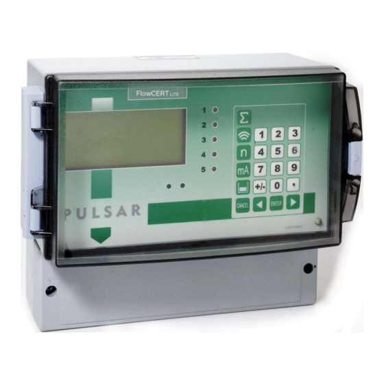
About the FlowCERT LITE The FlowCERT open channel flow meter is a state of the art ultrasonic LITE flow metering and control system which provides comprehensive flow monitoring with data logging (optional) and control functions for a complete range of flumes, weirs and channels. Easy calibration via the “Quick Set Up”... -
Page 11: Functional Description
The system utilises the unique DATEM software (Digital Adaptive Tracking of Echo Movement). This is a proven digital mapping technique developed especially for the Pulsar Ultra range, which gives the system unequalled ability when identifying the “true target level” in the face of competing echoes from pipes, pumps or other obstructions. -
Page 12: Product Specification
5 x M20 underside, 4 x 18mm dia (PG11) at rear Transducer cable extensions 3-conductor 20AWG screened Maximum separation 3,280 ft (1000 metres) for greater separation distances please consult Pulsar Environmental Mounting Indoor/Outdoor Relative Humidity (IP Rating) IP65 (NEMA 4X) when closed, IP20 when open... - Page 13 4000A breaking capability to comply with certification of the Exm version of dB series transducers. Pulsar Process Measurement Limited operates a policy of constant development and improvement and reserve the right to amend technical details as necessary. Page...
-
Page 14: Ec Declaration Of Conformity
EC DECLARATION OF CONFORMITY Page 6... -
Page 15: Chapter 2 Installation
Chapter 2 Installation Power Supply Requirements FlowCERT can operate from AC supply or from a DC battery and is LITE designed for use in temperatures between -4 F to +140 F (-20 C to +50 The AC is 115V+5%/-10% 50/60Hz. The DC is 22-28V. In all cases the FlowCERT will typically consume 6W of power, with a maximum of LITE... -
Page 16: Location
Location All electronic products are susceptible to electrostatic shock, so follow proper grounding procedures during installation. FlowCERT must be mounted in a non-hazardous (safe) area, and the LITE transducer fitted in the hazardous area. FM APPROVED TRANSDUCERS Class I, Div. 1, Group A, B, C & D Class II, Div. -
Page 17: Dimensions
Dimensions The dimensions of the wall fixing holes are as shown below. FlowCERT should be mounted by drilling three holes suitable for size LITE 8 screws (length to suit your application), and fixing the top screw in place. Hang the unit on this and fix the two remaining screws by removing the terminals access cover to access the pre drilled holes. - Page 18 The full dimensions of the enclosure are as shown below. Page 10...
-
Page 19: Terminal Connection Details
There are 6 cable gland knock-outs on the base of the wall mount FlowCERT Lite (5 x 0.79" (20mm), 1 x 0.63" (16mm)) and 4 on the rear (4 x 0.73" (18mm)). Select which ones you wish to use, and remove them by using a circular cutter, such as a tank cutter. - Page 20 Terminal Connections Important Information All terminal connection screws should be tightened to 4.5in.lbs. (0.5Nm) Care should be taken not to over tighten the screws. Power FlowCERT can operate from mains AC and automatically from DC or LITE battery backup in the event of power failure, or can be operated permanently from DC or batteries.
- Page 21 0 volts terminal. When installing a transducer in a hazardous area use an approved transducer, from the Pulsar dB range, suitable for the proposed application. For EEx m (Zone 1) applications a transducer certified to FM Class I Div 1 Group A, B, C &...
- Page 22 Important Information Please note that if the output of the ultrasonic transducers used with the FlowCERT L are capable of emitting sound pressure levels in excess of 85dBA (above a reference sound pressure level of 20µPA), then the FlowCERT L must be located remote from the transducer such that a sound pressure level of 85dBA is not exceeded when standing at the FlowCERT L...
-
Page 23: Voltage Selector And Fuse Location
The unit is connected as follows: Description Temperature FlowCERT Sensor LITE Power Supply Terminal 1 Terminal 29 Return Terminal 2 Terminal 28 Temp Source (P852), should be set to option 4 or 5 depending on the sensor range, set 4 for type A and 5 for type B (see above), the range is specified on the label of the sensor. -
Page 24: Preparation For Operation
Important Information Before applying AC power (mains), make sure the supply is 115V Never operate the FlowCERT L with terminal access exposed. An external switch or circuit breaker should be installed near to the FlowCERT L to allow the supply to be removed during installation and maintenance. -
Page 25: Maintenance
, except the LITE mains fuse. If you experience any problems with the unit, then please contact Pulsar Process Measurement for advice. Important Information Please note that the onboard Lithium battery, mounted to the processor PCB, is not user serviceable. -
Page 26: Chapter 3 How To Use Your Flowcert Lite
Chapter 3 How To Use Your FlowCERT LITE Operating the Controls Display The display provides information on the current mode of operation, and status of the remote communication. Whilst in the Run Mode it will display the current level reading and its units of measure, along with status messages with regards to the Transducer, Echo reception and Fail Safe Mode. -
Page 27: Run Mode
3) Auxiliary Display, scrolling twelve digit display. Run Mode, displays measurement units (P104), status messages on signal and transducer, detail of Hot Key function selected. It can be also programmed to provide notification messages on alarms and pumps etc. for full details please refer to Display Parameters in the relevant parameter listing. -
Page 28: How To Access Program Mode
How to Access Program Mode Wall and Fascia mount To enter program mode, you simply enter the passcode, via the keypad, followed by the ENTER key. The default passcode is 1997, so you would press the following: Note There is a time-out period of 15 minutes when in program mode, after which time run mode will be resumed if you do not press any keys. - Page 29 Hot Keys There are five hot keys on the keypad, which can be used to quickly access common parameters for viewing only, while in Run Mode. Pressing the hot key once will display the first parameter, then repeated pressing will display the others, then the FlowCERT reverts to Run Mode.
- Page 30 Menu Keys The menu keys have the following functions: Menu Key Function 1) Arrow keys for moving left and right around the menu system. 2) Used in test mode to simulate the level moving up and down. 1) Used to confirm each action (for example select a menu option) or when entering a parameter number or value.
- Page 31 There are two means of editing parameters, directly or using the menu system. Each is now described. Using the Menu System The menu system has been designed to make the changing of parameters very simple. There are two levels of menu: Main Menu and Sub Menu. On the display there is a line of text that displays the menu system.
- Page 32 Note You can tell which part of the menu system you are in, as the up/down level indicators, (arrows) next to the bargraph will indicate as follows: Top level menu: Down arrow on, to indicate you can move down. ...
-
Page 33: Test Mode
Test Mode Test mode is used to simulate the application and confirm that all parameters and relay setpoints have been entered as expected. During simulation, there is a choice of whether the relays will change state (hard simulation) or not (soft simulation), but the LED’s will always change colour as programmed, and the mA output will change in accordance to the chosen mode of operation. -
Page 34: Using The Rs232 Serial Interface
Using the RS232 Serial Interface The RS232 serial interface is used to communicate between the FlowCERT and a PC using the optional Ultra PC and other associated Pulsar LITE software packages, to obtain information such as data logging and view echo traces upload, download and save parameter files. - Page 35 /BACKUP2 (take backup of parameters to area 2) /RESTORE1 (restore parameters from area 1) /RESTORE2 (restore parameters from area 2) Please consult Pulsar Process Measurement or contact your local Pulsar representative for further details and a full list of available commands. Page...
-
Page 36: Parameter Defaults
Parameter Defaults Factory Defaults Factory Defaults When first installing the FlowCERT , or subsequently moving LITE or using the unit on a new application, before proceeding to program the unit for its intended application it is recommended that you ensure that all parameters are at their default values by completing a Factory Defaults P930, as described in the relevant unit type parameter guide. - Page 37 This page left blank intentionally Page...
-
Page 38: Chapter 4 Quick Setup Guide
Chapter 4 Quick Setup Guide This quick set-up guide shows you how to get up and running within a few minutes of installing your FlowCERT LITE Enter Program Mode First you need to go from run mode into program mode. Assuming the passcode is the default 1997, then you should enter this. - Page 39 Choose Your Application There are five categories of Primary Measuring Device, which are all described in this chapter. They are exponential, BS3860 flumes, BS3860 weirs, special and universal. Calculations for flow can be performed using absolute or ratiometric calculations. The answer will be the same, the choice of calculation method being limited to the amount of information available, with regards to the primary measuring device.
- Page 40 Once you have chosen your application you will be asked a series of questions which are answered by choosing the appropriate option as detailed in the flow chart below. Once all of the questions have been answered you will be prompted to provide further information, as detailed in the tables below, in order to complete the programming of the unit.
-
Page 41: Quick Setup Menu
The Quick Setup Menu detailing the questions you will be asked when setting up your FlowCERT , via the Quick Setup is shown below. LITE Quick Setup Menu Quick Setup PMD Type 0 = Off (No Calculation) 1 = Exponential 2 = BS3680 Flumes 3 = BS3680 Weirs 4 = Not Available... - Page 42 Wait ….. Parameter Default Description P101 1 = dB3 Type of Transducer to be used. Transducer P706 6 = Mil. USG Units of flow as on display and used Volume Units for calculations. 1=litres 2 = cubic metres 3=cubic feet 4 = UK gallons 5=US gallons 6 = Mil.USG...
- Page 43 Parameter Default Description P823 1=/1000 Sets the factor by which the Totaliser calculated volume will be divided or Multiplier multiplied by before being displayed. 1 = /1000 2 = /100 3 = /10 4 = *1 5 = *10 6 = *100 7 = *1,000 8 = *10,000 9 = *100,000...
- Page 44 For More Options Hit Enter Parameter Set Value Description P213 / P214 depends on Set required Alarm Setpoints. Relay 1 application ON/OFF P223 / P224 depends on Set required Alarm Setpoints. setpoints Relay 2 application ON/OFF P233 / P234 depends on Set required Alarm Setpoints.
-
Page 45: Exponential Devices
Exponential Devices If the primary measuring device is a simple exponential device then an exponent value is required. The FlowCERT will automatically enter LITE the exponent value for the device chosen as detailed in the table below. Exponent Type Exponent P717 Suppressed Rectangular 1.50 Weir... -
Page 46: Point Of Measurement
Point of Measurement The transducer must be above the maximum head P704 by at least the near blanking distance P107. For Suppressed/Contracted Rectangular, Trapezoidal and V-notch, weirs, the head is measured upstream at a minimum distance of 3 times maximum head from the weir plate to ensure the surface of the liquid is not affected by turbulence or drawdown. - Page 47 For a Leopald Lagco flume the head is measured at a point upstream of the beginning of the converging section as detailed in the table below. (See DRWG 4 Flume Size Point of Measurement inches inches 100 - 305 4 - 12 1065 1220 1370...
-
Page 48: Calculations
Calculations BSOLUTE If the flow calculation is to be absolute P702 = 1 the flow will be calculated using the formula (s) as follows: Exponent Type Formula Exponent K Factor Suppressed Q=KLh 1.50 Automatically Rectangular Where: Automatically calculated, Weir Q =Flow selected by dependent on (Without End... - Page 49 Exponent Type Formula Exponent K Factor V-Notch Weir Q=Kh 2.50 Automatically Where: Automatically calculated, Q =Flow selected by dependent on K=K factor FlowCERT measurement, h=head flow and time LITE =exponent units chosen. Enter value as Enter value as Other Q=Kh required required Contracted...
-
Page 50: Example 1 'V' Notch Weir
Example 1 ‘V’ Notch Weir In this example it is required to calculate the flow through a Simple Exponential Device, which on this occasion is a V-Notch Weir. The K factor for the weir is unknown so ratiometric calculation will be used, there is no requirement for alarms and the flow rate is to be displayed in Mil USG/day. - Page 51 To program the FlowCERT for Example 1 V-Notch Weir by using LITE the Quick Setup menu proceed as follows. If required access the Program Mode Key in the passcode 1997 and press ENTER Using the ‘right’ arrow key go to the Quick Setup menu press ENTER and as prompted, by the questions, select the relevant option and press ENTER.
-
Page 52: Bs3680 Flumes
BS3680 Flumes Point of Measurement The transducer must be above the maximum head P704 by at least the near blanking distance P107. For a Rectangular and U-throated flume, the head is measured at 3 to 4 times the maximum head upstream from the beginning of the converging section, to ensure the surface of the liquid is not affected by turbulence. -
Page 53: Calculations
Calculations Rectangular Flume BSOLUTE If the flow calculation is to be absolute P702 = 1 the flow will be calculated using the formula: q = (2/3) Where: q = flowrate gn = gravitational acceleration (nominal value = 980.66 cm/s = shape coefficient (value = 1) = velocity coefficient calculated by FlowCERT P721 LITE... - Page 54 U-Throated Flume BSOLUTE If the flow calculation is to be absolute P702 = 1 the flow will be calculated using the formula: q = (2/3) Where: q = flowrate = gravitational acceleration (nominal value = 980.66 cm/s = head shape coefficient calculated by FlowCERT P724 LITE = velocity coefficient calculated by FlowCERT...
-
Page 55: Example 2 Bs3680 U-Throated Flume
Example 2 BS3680 U-Throated Flume In this example it is required to calculate to BS3680 the flow through a U- Throated Flume without any hump. Absolute calculation will be used, and there is a requirement for an alarm to indicate a low flow condition which will be set to Relay 1. - Page 56 To program the FlowCERT for Example 2 BS3680 U-Throated LITE Flume by using the Quick Setup menu, proceed as follows. If required access the Program Mode Key in the passcode 1997 and press ENTER Using the ‘right’ arrow key go to the Quick Setup menu press ENTER and as prompted, by the questions, select the relevant option and press ENTER.
-
Page 57: Bs3680 Thin Plate Weirs
BS3680 Thin Plate Weirs Point of Measurement The transducer must be above the maximum head P704 by at least the near blanking distance P107. For a Rectangular and V-notch weirs, the head is measured at a point 4 to 5 times the maximum head upstream from the weir plate, to ensure the surface of the liquid is not affected by turbulence or drawdown. - Page 58 ATIOMETRIC If the flow calculation is to be ratiometric P702 = 2 the flow will be calculated using the formula: q= q ecal ecal Where: q = flowrate = flowrate at maximum head P705 = discharge coefficient calculated by FlowCERT P723 LITE = discharge coefficient at maximum head...
-
Page 59: Example 3 Bs3680 Rectangular Weir
Example 3 BS3680 Rectangular Weir In this example it is required to calculate to the flow through a BS3680 Rectangular weir. Absolute calculation will be used, and there is a requirement for an alarm to indicate a high flow condition to be set to Relay 3. - Page 60 To program the FlowCERT for Example 3 BS3680 Weir by using the LITE Quick Setup menu, proceed as follows. If required access the Program Mode Key in the passcode 1997 and press ENTER Using the ‘right’ arrow key go to the Quick Setup menu press ENTER and as prompted, by the questions, select the relevant option and press ENTER.
-
Page 61: Bs3680 Rectangular Broad Crested Weir
BS3680 Rectangular Broad Crested Weir Point of Measurement The transducer must be above the maximum head P704 by at least the near blanking distance P107. The head is measured at a point 3 to 4 times the maximum head upstream from the weir crest, to ensure the surface of the liquid is not affected by turbulence or drawdown. - Page 62 ATIOMETRIC BS3680 Rectangular Weir If the flow calculation is to be ratiometric P702 = 2 the flow will be calculated using the formula: q= q ecal ecal Where: q = flowrate = flowrate at maximum head P705 = discharge coefficient calculated by FlowCERT P723 LITE = discharge coefficient at maximum head...
-
Page 63: Special Devices
Special Devices Point of Measurement The transducer must be above the maximum head P704 by at least the near blanking distance P107. In the case of a Palmer Bowlus flume the point of head measurement should be half the value of Dim “A” P710 upstream of the device. For an H-Flume the head measurement is taken at a point downstream from the flume entrance as detailed in the table below: Flume size... -
Page 64: Calculations
V-notch angle weirs, the head is measured upstream of the weir plate at a minimum distance of 3 times maximum head to ensure the surface of the liquid is not effected by turbulence or drawdown. See Exponential devices, above, for further details. Calculations Palmer Bowlus Flume and H-Flume BSOLUTE... -
Page 65: Universal Calculations
ATIOMETRIC V-Notch Angle Weir (Non BS 3680) If the flow calculation is to be ratiometric P702 = 2 the flow will be calculated using the formula: q= q (h+kh/h +kh) Where: q = flowrate = flowrate at maximum head P705 = head kh = compensated head Universal Calculations... -
Page 66: Chapter 5 Parameter Guide
Chapter 5 Parameter Guide This section outlines all parameters available in the FlowCERT , as LITE they appear in the menu system. Shown below is a set of charts illustrating the menu system and location of all parameters available in the FlowCERT LITE For further details and full description of all parameters refer to Chapter 5 Parameter Listing and Descriptions. -
Page 67: Application Menu
Application Menu Operation Distances P100 P104 Mode Measurement Units P101 Transducer P105 Empty Level P102 Material P106 Span P107 Near Blanking P108 Far Blanking Page... -
Page 68: Relays Menu
Relays Menu Relay 1 Relay 2 Relay 3 Relay 4 Relay 5 P210 P220 P230 P240 P250 Type Type Type Type Type P211 P231 P241 P251 P221 Function Function Function Function Function P232 P252 P212 P222 P242 Alarm ID Alarm ID Alarm ID Alarm ID Alarm ID... -
Page 69: Data Logs Menu
Data Logs Menu Totaliser Temperature Audit P580 Min. Temp P460 Total Date 1 P581 Min. Temp. P461 Date Totaliser 1 P582 P462, 464, Min. Temp. 466, 468, 470, Time 472, 474, 476 Total Dates 2 to 9 P583 P463, 465, Max. -
Page 70: Ocm
Average Dimensions Calculation Breakpoints Tables Setup Flow P700 PMD P710 P730 P796 P863 P720 Dimension “A” Type Head Reset Average Area B’points Breakpoint 1 Flow P701 P711 P721 Dimension “B” P731 Primary P797 P864 Calculation 1 Flow Measuring Number Average Breakpoint 1 Time Device... -
Page 71: Display Menu
Display Menu Totaliser Options Fail Safe Auxiliary Bargraph P800 P808 P810 P829 P820 Display Fail Mode Units Totaliser Bargraph Units P809 P811 P801 Fail Time P821 Alarms Decimal Totaliser Places P812 Pumps P802 P822 Display P813 Totaliser Offset Control Decimal P804 P814 Display... -
Page 72: Compensation Menu
Compensation Menu Offset Temperature Velocity P851 P852 P860 Measurement Temperature Sound Offset Source Velocity P854 Fixed Temperature Stability Menu Damping Indicator Rate Filters P870 P872 P874 P880 Fill Fill Rate Update Gate Mode Damping Indicator P875 P881 P871 P873 Rate Time Fixed Distance Empty Empty... -
Page 73: Echo Processing Menu
Echo Processing Menu Xdr. 1 Status P900 Xdr. 1 Status P901 Echo Confidence P902 Echo Strength P903 Average Noise P904 Peak Noise P905 Sensitivity P906 Side Clearance Page... -
Page 74: System Menu
System Menu Date System Daylight Passcode Backup & Info Colour Saving Time P926 P921 P925 P931 P935 P970 Software Enable Code Date Parameter Revision Backup Colour Enable P922 P932 P927 Passcode Time P936 P971 Hardware Alarm P933 Revision Colour Difference Date P928 Format... -
Page 75: Device Comm Menu
Device Comm Menu RS232 RS485 Set Up Remote Set Up (Optional) Alarm If Comms. Type P061 If Comms. Type P144 PROFIBUS Comms Baud MODBUS Call Type P145 P130 Tel. No. 1 Device Mode P146 P131 Tel. No. 2 Protocol P147 P132 P132 Tel. -
Page 76: Test Menu
Test Menu Simulation Hardware P980 P990 Simulate Self Test P981 P991 Hardware Test Increment P992 P982 mA Out Test Rate P994 P983 Transducer Test Start Level P995 P984 Keys Test Incremental Change P996 Relay Test Page 68... - Page 77 Page...
-
Page 78: Chapter 6 Parameter Listing And Descriptions
Chapter 6 Parameter Listing and Descriptions Application Parameters Operation P100 Mode of Operation This parameter sets the mode of operation, when in run mode, and can be set to one of the following: Option Description Display shows the distance from the 1 = Distance (Default) transducer face to the surface. -
Page 79: Dimensions
Dimensions P104 Measurement Units This parameter sets the units you want to use for programming and display Option Description 1 = metres All units of measure are METRES 2 = cm All units of measure are CENTIMETRES 3 = mm All units of measure are MILLIMETRES 4 = feet... - Page 80 P106 Span This parameter should be set to the maximum distance from the Empty Level (P105) to the maximum material level. It is automatically set to be equal to the Empty Level (P105) less the Near Blanking distance (P107), when you set the empty level. P107 Near Blanking Distance This parameter is the distance from the face of the transducer that is not measurable, and is pre-set to the minimum value dependant on the Xducer...
-
Page 81: Relay Parameters
Relay Parameters All relay related parameters are prefixed with a 2**. The second digit of the three figure parameter number denotes the relay number as follows: 21* parameters for Relay 1 22* parameters for Relay 2 23* parameters for Relay 3 24* parameters for Relay 4 25* parameters for Relay 5 The third digit selects specific parameter for the setting of the relays, which... - Page 82 P210, P220, P230, P240, P250 - Relay Type This parameter defines what type each relay should be, see the table below for available options. Option Description Relay not in use or programmed and LED 0= Not In Use (Default) will always be off. 1= Alarm Relay is programmed as an alarm relay, which will de-energise ON, and energise...
-
Page 83: Alarms
Alarms When P210, 220, 230, 240, 250 =1 (Alarm) The second parameter for each relay determines the function of the alarm. P211, P221, P231. P241, P251 - Relay Function This parameter defines what function the alarm will respond to as follows. Option Description Relay will not operate. - Page 84 The third parameter for each relay determines the alarm ID for the relay you wish to set. P212, P222, P232, P242, P252 - Relay Alarm ID When P211, 221, 231, 241 251 = 1 (Level), 2 (Rate of Change) or 3 (Temperature.) This parameter defines which alarm type, or identification, the relay should respond to, as follows.
- Page 85 Alarm ID Description Setpoints Relay goes “ON” if 6= In bounds Relay Setpoints, value is inside the zone P213, 223, 233, between the two 243, 253 and P214, setpoints. 224, 234, 244, 254 can be set in any order as the unit ‘knows’...
- Page 86 The fourth parameter and the fifth parameter for each relay set the Alarm “ON” and “OFF” points. For a high alarm the “ON” is set higher than “OFF”. For low alarm then “ON” is set lower than “OFF”. See the appropriate alarm ID, table (P212, 222, 232, 242, 252) for further information.
-
Page 87: Pumps
Pumps When P210, 220, 230, 240, 250 = 2 (Pump) When a relay is being used for a pump function, the second parameter determines the pump duty that will be used to determine the operating cycle. P211, P221, P231, P241, P251 - Relay Function, This parameter defines which pump duty the relay should respond to as follows. - Page 88 Pump Duty Description 5= Duty backup and assist First pump comes on, if it cannot cope, it goes off and next pump comes on (duty backup). This continues until the last pump comes on and if it cannot cope the first pump comes back on to assist the last pump (duty assist) if the level continues to rise all other pumps will come on (assist) in turn until the level...
- Page 89 Pump Duty Description 8= First On First Off, The first pump switched on is the first alternate duty assist pump to be switched off, etc. regardless of the set points, so the setpoints are dynamically changed to enable this. When a service ratio duty is being used, 9 = Service Ratio Standby on all other pumps in use, the standby pump can be started on a ratio basis...
- Page 90 The fourth parameter and the fifth parameter for each relay set the pump “ON” and “OFF” points, which are entered in Measurement units P104. For pump down the “ON” is set higher than “OFF”. For pump up then “ON” is set lower than “OFF”. See the appropriate pump duty, function table (P212, 222, 232, 242, 252) for further information.
-
Page 91: Control
Control When P210, 220, 230, 240, 250 = 3 (Control) When a relay is being set up as a control relay, the second parameter that will be displayed in the menu determines its function. P211, P221, P231, P241, P251, Relay Function, This function allows the relay to be assigned to specific control functions (other than pumps and alarms) several of these functions work in relation to time. - Page 92 The third parameter for each relay determines the assignment or condition of the relay, where required. When P211, 221, 231, 241, 251 = 2 (Step Time) If the relay is selected for Step Time, then this parameter is used to assign the relay to the 0 = Open condition (increase level) or 1 = Close condition (decrease level).
- Page 93 P215, P225, P235, P245, P255 Relay Setpoint 3 This parameter is used to determine the Limit Time between each Drive Period. Relay Setpoints are entered in Minutes, during which time the relay will remain OFF. See the appropriate relay Function tables (P211, 221, 231, 241, 251) for further information.
-
Page 94: Miscellaneous
Miscellaneous When P210, 220, 230, 240, 250 = 4 (Miscellaneous) When a relay is set to be a miscellaneous relay, the second parameter determines its function. P211, P221, P231, P241, P251 - Relay Function This function allows the relay to work in relation to a clock or a specific event and will be set to activate in relation to Real Time. - Page 95 The fourth parameter, and fifth parameter, are set to determine the switch points, “ON” and “OFF” for the relay. See miscellaneous function table (P211, 221, 231, 241, 251) for further information. When P211, 221, 231, 241, 251 = 1 (Clock) P213, P223, P233, P243, P253 - Relay Setpoint 1 Relay Setpoints are entered in Hours &...
-
Page 96: Common Parameters
Common Parameters P216, P226, P236, P246, P256 - Relay Allocation This parameter determines which input the relay will act on. In most cases, this will not need to be changed from the default. Option Description Relay acts on Xducer 1calculated levels. 1= Xducer 1 (Default) P217, P227, P 237, P247, P257 - Relay Closures The FlowCERT... -
Page 97: Data Log Parameters
Data Log Parameters The data log parameters contains the following information. Totaliser Audits P460 to P479 Total Audits Parameters P460-P479 show the date and total flow for the last ten days, the first on the list are the most recent and last ones are the oldest. When all ten total audits are full the oldest is pushed out and all totals increment through to allow the new days total to be registered in the first days total audit parameter allocation. - Page 98 P584 Maximum Temperature Date This parameter displays the date when the maximum temperature was recorded. P585 Maximum Temperature Time This parameter displays the time when the maximum temperature was recorded. P586 Current Temperature This parameter displays the current temperature. Page 90...
-
Page 99: Ocm Parameters
OCM Parameters PMD Setup P700 Primary Measuring Device Type This parameter is used to select the type of Primary Measuring Device and enable additional parameters required to calculate the flow of the particular Primary Measuring Device chosen (P701). Options are as follows: 0 = Off (Default) 1 = Exponent 2 = BS3680 Flume... - Page 100 If P700 = 3 (BS 3680 Weir) Select from the following options: 1 = Rectangular 2 = V-Notch Full 90 degree (full 90 3 = V-Notch 53 degree 8’ (half 90 4 = V-Notch 28 degree 4’ (quarter 90 5 = Broadcrested (Rectangular) Weir If P700 = 5 (Special) Select from the following options: 1 = Palmer-Bowlus Flume...
- Page 101 P703 Minimum Head This parameter is used to enter the distance, above empty, that represents zero head and flow. This feature is used in Primary Measuring Devices where the zero reference is at a higher level than the channel bottom, at the point of measure.
-
Page 102: Dimensions
P707 Time Units Select the Time Units to be used with the Volume Units to determine the desired flow rate from the options below: Option Description 1= per Second Flowrate will be calculated and displayed in Volume units/Second 2= per Minute Flowrate will be calculated and displayed in Volume units/Minute Flowrate will be calculated and displayed in... - Page 103 P713 Dimension D This parameter is used to enter to enter dimension “D” of the Primary Measuring Device, where applicable, see table below for further details. P710 P711 P712 P713 Pimary Measuring Device Dim “A” Dim “B” Dim “C” Dim “D” P700 = 1 Exponent Crest P701 = 1 Supp.
- Page 104 P714 Roughness Coefficient (Ks) When P700 = 2, BS3680 Flume this parameter is used to enter the roughness coefficient of the flume in millimetres, see table below for further details. Value of Ks Good Normal Example Value Surface Classification Plastics, etc Perspex, PVC or other smooth faced 0.003 plastics...
- Page 105 P717 Exponent This parameter is used to enter the exponent value when: P700 PMD Type = 1 Exponent and P701 Primary M.D = 7 Others. P718 K Factor This parameter is used to enter the K Factor when: P700 PMD Type = 1 Exponent and P702 Calculation = 1 Absolute see table below for further details.
-
Page 106: Calculations
Calculations The following parameters P720 to P725 are values calculated by the unit, dependent on application, and are “Read Only”, therefore have no default values. P720 Area Displays the calculated value of the area when, P700 = 2 BS3690 flumes. P721 Cv Displays the calculated value for Cv when, P700 = 2 BS3680 flumes. -
Page 107: Tables
Tables P796 Reset Breakpoints This parameter allows the resetting, to the default value, of all previously set breakpoints (P730-793), without having to access them individually. When it is necessary to reset or amend particular breakpoints this can be achieved by directly accessing the desired parameter (P730-793) and changing as required. -
Page 108: Display Parameters
Display Parameters Options P800 Display Units This parameter determines whether the reading displayed is in Measurement Units (P104), or as a percentage of span. Option Description Display is in selected units dependant on 1 = Measured (Default) Mode (P100) Display percentage span 2 = Percentage... -
Page 109: Failsafe
Failsafe P808 Fail-safe Mode By default, if a fail-safe condition occurs, then the display, relays and the mA output are held at their last known values until a valid reading is obtained. If required, then you can change this so that the unit goes to high (100% of span), or low (empty) as follows: Option Description... -
Page 110: Auxiliary
Auxiliary P810 Units This parameter determines whether the Measurement units (P104) are displayed on the auxiliary line of the display in run mode. Option Description 0 = No Measurement units will not be displayed Measurement units will be displayed 1 = Yes (Default) P811 Alarms Messages This parameter determines whether notification messages are displayed on the auxiliary line of the display in run mode when an alarm relay is switched... -
Page 111: Totaliser
P814 Miscellaneous Messages This parameter determines whether notification messages are displayed on the auxiliary line of the display in run mode when a miscellaneous relay is switched on or off. The message is in the form “Clock ON”. Option Description 0 = No (Default) Misc. - Page 112 P823 Totaliser Multiplication Factor Use this parameter if the totaliser increments by to large or small amount, enter the factor by which the actual flow rate is multiplied by before incrementing the totaliser. E.g. if flowrate is being calculated and displayed in ltrs/second and it is desired to increment the totaliser in cubic metres select 7 = *1000.
-
Page 113: Bargraph
Bargraph P829 Bargraph By default the bargraph will be representative of the reading obtained, as determined by the Mode P100. This parameter is automatically set to the correct default option when selecting the Mode P100 and Xducer (P101), and under normal circumstances will not require changing. The options, dependant on the value entered for Mode P100, are as follows: Option Description... -
Page 114: Operation
Operation P831 mA Mode This parameter determines how the ma Output relates to what is measured. By default it operates exactly the same as the display (P100), but it can be set to operate as follows: Option Description 0 = Default mA output relative to Mode P100 1 = Distance mA output relative to distance. -
Page 115: Limits
Limits P836 mA Low Limit This parameter sets the lowest value that the mA output will drop to, the default is 0mA, but you can override this if the device you connect to cannot for example accept less than 2mA, yet you want to use the 0-20mA range. Default = 0.00mA P837 mA High Limit This parameter sets the highest value that the mA output will rise to, the... -
Page 116: Allocation
Allocation P841 mA Allocation By default the mA output will be representative of the reading obtained, as determined by the Mode P100. This parameter is automatically set to the correct default option when selecting the Mode P100 and Xducer (P101), and under normal circumstances will not require changing. -
Page 117: Temperature
Temperature P852 Temperature Source This parameter determines the source of the temperature measurement. By default it is set to External Range “A” (P852=4), which will use an external temperature sensor with range -25˚C to 50˚C. If for any reason, no temperature input is received, then the Fixed Temp value is used, as set by P854. -
Page 118: Velocity
Velocity P860 Sound Velocity This parameter allows for the velocity of sound to be changed according to the atmosphere the transducer is operating in. By default the velocity is set for sound travelling in air at an ambient temperature of 20 degrees centigrade. -
Page 119: Indicator
Indicator P872 Fill Indicator This parameter determines the rate at which the LCD fill indicator activates. Default = 10m/min P873 Empty Indicator This parameter determines the rate at which the LCD empty indicator activates. Default = 10m/min Rate P874 Rate Update This parameter determines the way in which the rate is calculated. -
Page 120: Filters
Please consult Pulsar for further information and assistance on changing the value of this parameter, Default = 0 (Fixed) -
Page 121: Echo Processing Parameters
P905 Sensitivity This parameter determines the sensitivity of the unit. Please consult Pulsar for further information and assistance on changing the value of this parameter. -
Page 122: System Parameters
This parameter is used to set the distance by which the DATEM trace will “stand off” from around unwanted echoes such as obstructions. Please consult Pulsar for further information and assistance on changing the value of this parameter. System Parameters... -
Page 123: System Information
System Information The following three parameters do not affect how the unit performs, but details, contained in them, may be required, by Pulsar, when making technical enquiries. P926 Software Revision This parameter will display the current software revision. It is read only, and cannot be changed. -
Page 124: Date & Time
Date & Time The date and time is used, to control specific relay functions and date stamp certain events that are contained in the Data Logs. It is also used in conjunction with the system watchdog that keeps an eye on the times the unit has started. -
Page 125: Watchdog
P937 General Control/Pump Relay Colour This parameter selects the colour that a pump relay should be when it is in its “ON” state. The default is 2 = green, but can be changed to ‘no colour’, red or yellow. P938 Control Relay Colour This parameter selects the colour that a control relay should be when it is in its “ON”... -
Page 126: Daylight Saving Time
Daylight Saving Time Important Information In order to ensure the correct operation of Daylight Saving Time P932 Time should be checked, and adjusted if necessary, to ensure that it is set for the current valid time.. P970 DST Enable When Enabled (set to 1) the internal clock will be automatically adjusted to compensate for the difference between standard time and Daylight Saving Time. - Page 127 P974 Start Week This parameter will determine the week of the month (P975) in which Daylight Saving Time is to start. Option Description 1= Week 1 DST will start on day (P973) in the first week (P974) of the month (P975). 2= Week 2 DST will start on day (P973) in the second week (P974) of the month (P975).
- Page 128 P977 End Day Use this parameter to enter the day of the week (P974) that Daylight Saving Time is to end. Option Description 2= Monday DST will end on a Monday 3= Tuesday DST will end on a Tuesday 4= Wednesday DST will end on a Wednesday 5= Thursday DST will end on a Thursday...
-
Page 129: Device Comm
P979 End Month This parameter is used to select the month, in which Daylight Saving Time will end. Option Description 1= January DST will end during the month of January 2= February DST will end during the month of February 3= March DST will end during the month of March 4= April... -
Page 130: Remote Alarm
Remote Alarm When a Modem is connected to, via the RS232 port, (Consult Pulsar or your local distributor for further details), the following parameters are used to set up the FlowCERT so that when the level reaches a specific alarm... - Page 131 P146 Tel. No2 This parameter is used to enter to enter the next 6 digits, following the ‘0’s, of the telephone number to be dialled. If there are less then 8 digits following the ‘0’s then just enter the digits required, if there are more than digits following the ‘0’s then enter the first 6 digits and then proceed to P147 and enter the remaining digits.
-
Page 132: Test Parameters
Test Parameters Simulation P980 Simulate Test mode is used to simulate the application and confirm that all parameters and relay setpoints have been entered as expected. During simulation, there is a choice of whether the relays will change state (hard simulation) or not (soft simulation), but the LED’s will always change colour as programmed, and the current output will change. -
Page 133: Hardware
P982 Rate In automatic mode, the rate at which the level will move up and down is determined by distance, P981 Increment and the time, P982 Rate which by default is set to 1min and can be changed as required. To increase the rate at which the level moves increase the Increment (P981) or decrease the Rate (P982). - Page 134 P991 Hard Test When this parameter is selected, the unit will test the following in turn. LED’s. Watch them change colour as shown on the display, and press, ENTER, if they operated as shown. Relays. Press a numeric key corresponding to the number of the relay you wish to test, and the relay will change state each time the key is pressed.
- Page 135 This page left blank intentionally Page...
-
Page 136: Chapter 7 Troubleshooting
Chapter 7 Troubleshooting This section describes many common symptoms, with suggestions as to what to do. Symptom What to Do Display blank, transducer not firing. Check power supply, voltage selector switch and fuse. Displays “No Xducer” Check wiring to transducer. Displays “Xducer Flt”... - Page 137 This page left blank intentionally Page...
-
Page 138: Parameter Record
Parameter Record PPLICATION Operation Parameter Details Entered Values Description Default P100 Mode 1 = Dist. P101 Xducer 1 = dB3 P102 Material 1= Liquid Distances Parameter Details Entered Values Description Default P104 Measurement Units 5=inches P105 Empty Level 106.299 inch P106 Span 101.378 inch... - Page 139 ELAYS Relay 1 Parameter Details Entered Values Description Default P210 R1 Type 0 = Off P211 R1 Function 0 = Off P212 R1 Alarm ID 1 = Off P213 R1 Set 1 0.000 P214 R1 Set 2 0.000 P215 R1 Set 3 0.000 P216 R1 Allocation...
- Page 140 Relay 4 Parameter Details Entered Values Description Default P240 R4 Type 0 = Off P241 R4 Function 0 = Off P242 R4 Alarm ID 1 = Off P243 R4 Set 1 0.000 inches P244 R4 Set 2 0.000 inches P245 R4 Set 3 0.000 P246...
- Page 141 Temperature Parameter Details Entered Values Description Default P580 Minimum Temperature Read Only P581 Min Temperature Date Read Only P581 P582 Min Temperature Time Read Only P583 Maximum Temperature Read Only P584 Max Temperature Date Read Only P585 Max Temperature Time Read Only P586 Current Temperature...
- Page 142 PMD Setup Parameter Details Entered Values Description Default P700 PMD Type 0 = Off P701 Primary M.D 1 = Off P702 Calculation 2 = Ratiom. P703 Minimum Head 0.000 inches P704 Maximum Head 101.378 inch P705 Maximum Flow 0.000 P706 Volume units 6 = MUSG P707...
- Page 143 Breakpoints Parameter Details Entered Values Description Default P730 Head Breakpoint 1 0.001 P731 Flow Breakpoint 1 -1.000 P732 Head Breakpoint 2 0.001 P733 Flow Breakpoint 2 -1.000 P734 Head Breakpoint 3 0.001 P735 Flow Breakpoint 3 -1.000 P736 Head Breakpoint 4 0.001 P737 Flow Breakpoint 4...
- Page 144 P773 Flow Breakpoint 22 -1.000 P774 Head Breakpoint 23 0.001 P775 Flow Breakpoint 23 -1.000 P776 Head Breakpoint 24 0.001 P777 Flow Breakpoint 24 -1.000 P778 Head Breakpoint 25 0.001 P779 Flow Breakpoint 25 -1.000 P780 Head Breakpoint 26 0.001 P781 Flow Breakpoint 26 -1.000...
- Page 145 ISPLAY Options Parameter Details Entered Values Description Default P800 Display Units 1 =Measured P801 Decimal Places P581 P802 Display Offset 0.000 inches P804 Display Conversion 1.000 P805 Display source 0 = Default Fail Safe Parameter Details Entered Values Description Default P808 Fail Mode 1 = Known...
- Page 146 mA O UTPUT Range Parameter Details Entered Values Description Default P830 mA Out Range 2 = 4 - 20 P581 Operation Parameter Details Entered Values Description Default P831 mA Out Mode 0 = Default P581 Set Point Parameter Details Entered Values Description Default P834...
- Page 147 OMPENSATION Offset Parameter Details Entered Values Description Default P851 Measurement Offset 0.0 mA Temperature Parameter Details Entered Values Description Default P852 Temperature Source 4=Ext.Range A P853 Allocation 0 = Xducer 1 P854 Fixed Temperature 20.00 Velocity Parameter Details Entered Values Description Default P860...
- Page 148 Filters Parameter Details Entered Values Description Default P880 Gate Mode 0 = Fixed P881 Fixed Distance 7.87 inches P882 Process Filter 3 = Slow P884 Peak Percent 50.0% ROCESS Xducer Status 1 Parameter Details Entered Values Description Default P900 Xducer 1 Status Read Only P901 Echo Confidence 1...
- Page 149 Date & Time Parameter Details Entered Values Description Default P931 Date Current Date P932 Time Current Time P933 Date Format 1=DD:MM: LED Colours Parameter Details Entered Values Description Default P935 Off Colour 3 = Yellow P936 Alarm Colour 1 = Red P937 Pump/Gen.
- Page 150 EVICE RS232 Setup Parameter Details Entered Values Description Default P061 Comms Baud 19200 RS485 Setup (Optional) Modbus Parameter Details Entered Values Description Default P130 Device Mode 0 = Off P131 Protocol 0 = Modbus RTU P132 Device Address P133 Device Baud 19200 P134 Parity...
Need help?
Do you have a question about the FlowCERT LITE and is the answer not in the manual?
Questions and answers