Table of Contents
Advertisement
Advertisement
Table of Contents

Related Manuals for Pulsar Ultra 3 (UL)


Summary of Contents for Pulsar Ultra 3 (UL)
- Page 1 ULTRA 3 (UL) NSTRUCTION ANUAL...
- Page 3 ARRANTY AND IABILITY Pulsar Process Measurement Limited guarantee for a period of 2 years from the date of delivery that it will either exchange or repair any part of this product returned to Pulsar Process Measurement Limited if it is found to be defective in material or workmanship, subject to the defect not being due to unfair wear and tear, misuse, modification or alteration, accident, misapplication or negligence.
-
Page 5: Table Of Contents
Contents Chapter 1 Start Here… ............................1 About this Manual ............................1 About the Ultra 3 ............................. 2 Functional Description ............................ 3 How to use this Manual ........................... 4 Product Specification............................5 EU Declaration of Conformity ........................7 Wall Mount .............................. 7 Fascia Mount ............................ - Page 6 Menu System and Parameter Guide ......................52 Top Level Menu .............................52 Application Menu ..........................53 Relays Menu ............................54 Data Logs Menu .............................55 Volume Menu ............................56 Display Menu ............................57 mA Output Menu ...........................57 Compensation Menu ..........................58 Stability Menu ............................58 Echo Processing Menu...........................59 System Menu ............................60 Device Comm Menu ..........................61 Test Menu ...............................62 Chapter 6 Pump ..............................63...
- Page 7 Calculations ............................112 Menu System and Parameter Guide ......................113 Top Level Menu ..........................113 Application Menu ..........................114 Relays Menu ............................115 Data Logs Menu ..........................116 OCM ..............................117 Display Menu ............................118 mA Output Menu ..........................118 Compensation Menu ...........................
- Page 8 Temperature............................167 Velocity..............................168 Stability Parameters ............................ 169 Damping .............................. 169 Indicator ............................... 169 Rate ..............................169 Filters ..............................170 Echo Processing Parameters ........................171 Transducer 1 Status ..........................171 System Parameters ............................173 Passcode............................... 173 Backup ..............................173 System Information ..........................173 Date &...
-
Page 9: Chapter 1 Start Here
Chapter 1 Start Here… Congratulations on your purchase of a Pulsar Ultra 3. This quality system has been developed over many years and represents the latest in high technology ultrasonic level measurement and control. It has been designed to give you years of trouble free performance, and a few minutes spent reading this operating manual will ensure that your installation is as simple as possible. -
Page 10: About The Ultra 3
Ultra 3 About the Ultra 3 is three units in one. Ultra 3 is a brand-new concept in ultrasonic level measurement. Within its memory are all the functions and settings of three different and separate ultrasonic devices. The Ultra 3 does not offer a multiple range of functions blended together which lead to complicated calibration and a compromise to the specification, Ultra 3 is the first ever system to offer the ability to dedicate the functionality of the unit to any of three specific duties i.e. -
Page 11: Functional Description
‘all new’ dB transducer range, the Ultra 3 lives up to its reputation as the most reliable ultrasonic level measurement system available. The Pulsar Ultra 3 ultrasonic level controller has been designed to provide maintenance-free fit and forget performance. Page... -
Page 12: How To Use This Manual
How to use this Manual Read the installation and operating instructions contained in, Chapters 2 and 3, carefully, they are applicable in every use of this product. Decide which “task” you wish your Ultra 3 to perform for you and then configure the unit using “Ultra Wizard”... -
Page 13: Product Specification
Product Specification Physical Wall Mount Outside dimensions 7.6 x 6.1 x 4.0 inch (188 x 160 x 107 mm) Weight Nominal 2.2lbs (1 kg) Enclosure material/description Polycarbonate, flame resistant to UL94-5V Cable entry detail 8 cable entry knock outs, 3 x M20 1 x M16 underside, 4 x PG11 at rear Fascia Mount Outside Dimensions... - Page 14 Exm version of dB series transducers. Remote Communicator Batteries 2 x AA alkaline batteries. Do not use NiCads. Pulsar Process Measurement Limited operates a policy of constant development and improvement and reserve the right to amend technical details as necessary. Page...
-
Page 15: Eu Declaration Of Conformity
EU Declaration of Conformity Wall Mount Page... -
Page 16: Fascia Mount
Fascia Mount Page... -
Page 17: Chapter 2 Installation
Chapter 2 Installation Power Supply Requirements Ultra 3 can operate from AC supply or from a DC battery and is designed for use in temperatures between -4 F to +140 F (-20 C to +50 C). The AC is 115V +5% / -10% 50/60Hz. The DC is 18-30V. In all cases the Ultra 3 will typically consume 6W of power, with a maximum of 10W. -
Page 18: Location
Location All electronic products are susceptible to electrostatic shock, so follow proper grounding procedures during installation. Ultra 3 must be mounted in a non-hazardous (safe) area, and the transducer fitted in the hazardous area. FM APPROVED TRANSDUCERS Class I, Div. 1, Group A, B, C & D Class II, Div. -
Page 19: Dimensions
Dimensions Wall Mount The dimensions of the wall fixing holes are as shown below. Ultra 3 should be mounted by drilling three holes suitable for size 8 screws (length to suit your application), and fixing the top screw in place. Hang the unit on this and fix the two remaining screws by removing the terminals access cover to access the pre-drilled holes. - Page 20 The full dimensions of the enclosure are as shown below. Page...
-
Page 21: Fascia Mount
Cable Entry There are 4 cable gland knock-outs on the base of the wall mount Ultra 3 (3 x 0.79" (20mm), 1 x 0.63" (16mm) and 4 on the rear (4 x 0.73" (18mm)). Select which ones you wish to use, and remove them by using a circular cutter, such as a tank cutter. - Page 22 The full dimensions of the Fascia mount enclosure are as shown below: Page...
-
Page 23: Terminal Connection Details
Important Information When mounting the fascia mount unit in to a panel, in order to maintain the panel IP rating the panel should be of smooth/painted finish and be machined, as per the details contained in this manual. Fit the unit through the hole then, using the components supplied place a plain washer then a spring washer followed by an elongated nut to each of the 4 off M3 threaded studs and tighten to 2.5lb in. -
Page 24: Fascia Mount
Fascia Mount The terminal details are as illustrated below. Important Information All terminal connection screws should be tightened to 4.5in.lbs. (0.5Nm). Care should be taken not to over tighten the screws. Page... - Page 25 Terminal Connections Important Information All terminal connection screws should be tightened to 4.5in.lbs. (0.5Nm). Care should be taken not to overtighten the screws. Power Ultra 3 can operate from mains AC and automatically from DC or battery backup in the event of power failure, or can be operated permanently from DC or batteries.
- Page 26 Transducer The transducer should be installed, and connected, in accordance with the installation instructions contained in the Transducer User Guide. The entire range of, standard dB transducers are certified for use in hazardous areas and different models, for each, are available for use in Zone 1 or Zone 0.
- Page 27 ATEX For EEx m (Zone 1) applications a transducer certified to Sira 02ATEX5104X is used, and must be supplied via a 4000A breaking fuse, which is fitted as standard to the Ultra3. For EEx ia (Zone 0) a transducer certified to Sira 02ATEX2103X is used, which must be connected to the Ultra 3 via an external Zener barrier.
-
Page 28: Fuse Location
Fuse Location Wall mount The mains fuse is located, inside the terminal compartment, to the left of the mains terminals, as illustrated below. Fascia mount The mains fuse is located under the removable cover at the bottom of the unit, as illustrated below Page... - Page 29 Important Information The rear metal case of the fascia unit must be connected to earth via the earthing stud located on the rear of the unit, see drawing above, using wiring to meet local requirements. Before applying AC power (mains), make sure the supply is 115V AC. Never operate the Ultra 3 with terminal access exposed.
-
Page 30: Preparation For Operation
✓ The relays are connected correctly. Maintenance There are no user serviceable parts inside Ultra 3, except the mains fuse. If you experience any problems with the unit, then please contact Pulsar Process Measurement for advice. Important Information Please note that the on-board Lithium battery, mounted to the processor PCB, is not user serviceable. -
Page 31: Chapter 3 How To Use Your Ultra 3
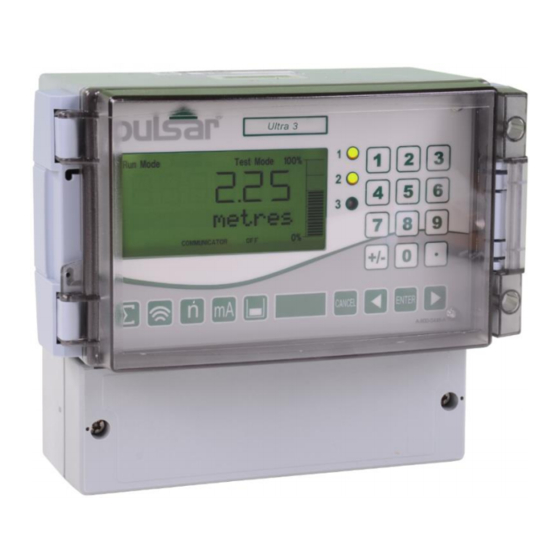
Ultra 3 Chapter 3 How To Use Your Operating the Controls Display The display provides information on the current mode of operation, and status of the remote communication. While in the Run Mode it will display the current level reading and its units of measure, along with status messages with regards to the Transducer, Echo reception and Fail Safe Mode. -
Page 32: Run Mode
3) Auxiliary Display, scrolling twelve-digit display. Run Mode, displays measurement units (P104), status messages on signal and transducer, detail of Hot Key function selected. It can be also programmed to provide notification messages on alarms and pumps etc. for full details please refer to Display Parameters in the relevant parameter listing. -
Page 33: Program Mode
Program Mode This mode is used to set up the Ultra 3 or change information already set. You must use either the built-in keypad (standard) or alternatively the unit can be set up with a PC via the RS 232 Serial Interface. Entering a value for each of the parameters that are relevant to your application provides all the programming information. - Page 34 Hot Keys There are five hot keys on the keypad, which can be used to quickly access common parameters for viewing only, while in Run Mode. Pressing the hot key once will display the first parameter, then repeated pressing will display the others, then the Ultra 3 reverts to Run Mode.
- Page 35 Menu Keys The menu keys have the following functions: Menu Key Function 1) Arrow keys for moving left and right around the menu system. 2) Used in test mode to simulate the level moving up and down. 1) Used to confirm each action (for example select a menu option) or when entering a parameter number or value.
- Page 36 There are two means of editing parameters, directly or using the menu system. Each is now described. Using the Menu System The menu system has been designed to make the changing of parameters very simple. There are two levels of menu: Main Menu and Sub Menu. On the display, there is a line of text that displays the menu system.
- Page 37 Note You can tell which part of the menu system you are in, as the up/down level indicators, (arrows) next to the bar graph will indicate as follows: • Top level menu: Down arrow on, to indicate you can move down. •...
-
Page 38: Test Mode
Test Mode Test mode is used to simulate the application and confirm that all parameters and relay setpoints have been entered as expected. During simulation, there is a choice of whether the relays will change state (hard simulation) or not (soft simulation), but the LED’s will always change colour as programmed, and the mA output will change in accordance to the chosen mode of operation. -
Page 39: Using The Rs232 Serial Interface
Using the RS232 Serial Interface The RS232 serial interface is used to communicate between the Ultra 3 and a PC using the optional Ultra PC and other associated Pulsar software packages, to obtain information such as data logging and view echo traces upload, download and save parameter files. - Page 40 Examples of other commands you can use are: /LEVEL (shows current level) /SPACE (shows current space) /HEAD (shows current OCM head) /FLOW (shows current OCM flow) /TEMPERATURE (shows current temperature) /CURRENTOUT (show the mA output value) /CURRENTIN (show the mA input value) /BACKUP1 (take backup of parameters to area 1) /BACKUP2 (take backup of parameters to area 2) /RESTORE1 (restore parameters from area 1)
-
Page 41: Parameter Defaults
Parameter Defaults Factory Defaults Factory Defaults When first installing the Ultra 3, or subsequently moving or using the unit on a new application, before proceeding to program the unit for its intended application it is recommended that you ensure that all parameters are at their default values by completing a Factory Defaults P930, as described in the relevant unit type parameter guide. - Page 42 This page left blank intentionally Page...
-
Page 43: Chapter 4 Ultra Wizard
Chapter 4 Ultra Wizard The Ultra Wizard menu allows you to turn Ultra 3 into anyone of three dedicated ultrasonic devices to exactly suit the requirements of your application. Ultra Wizard Menu To access the Ultra Wizard, you need to go from Run Mode to Program Mode. -
Page 44: Lev/Volume
Lev/Volume If you require to set up a level or volume application, with or without a choice of control functions then press “1” followed by “ENTER” the message “Loading ***” will be displayed and your Ultra 3 will be configured as a Level Star 3. Confirmation that configuration has been completed will be given by the unit type, software version and serial number being displayed briefly on the LCD and the unit advancing to the relevant “Quick Setup”... -
Page 45: Vantage 3
Vantage 3 The Vantage 3 level controller provides pump control with a complete range of pump “duties” being available. The Vantage 3 can measure from zero to 49.2 feet from the face of the transducer to the surface being monitored, dependent on the transducer used. The Vantage 3 can show level, space or distance on the display. - Page 46 This page left blank intentionally Page...
-
Page 47: Chapter 5 Level / Volume
Chapter 5 Level / Volume When Ultra Wizard = 1 Level/Volume Ultra 3 is configured as a Level Star 3 Quick Setup This quick set-up guide shows you how to get up and running within a few minutes of installing your Level Star 3. Before proceeding ensure that Ultra Wizard = 1 Level/Volume (Level Star 3). - Page 48 Note If you have already setup a common application, then there will be a number shown other than 0, and you will see messages showing what the current setup is. If you want to reset this and start again, press 0 (which will reset all the quick setup parameters), otherwise pressing ENTER will allow you to edit the parameters that have been set.
-
Page 49: Quick Setup Menu
The Quick Setup Menu detailing the questions you will be asked when setting up your Level Star, via the Quick Setup is shown below. Quick Setup Menu Quick Setup Application 1 = Level 2 = Volume 0 = No Control 1 = Control Down 2 = Control Up No. - Page 50 Wait …. Parameter Default Description P101 Transducer 2 = dB6 Type of transducer being used. P102 Material 1 = liquid Material in the vessel, either liquid or solid. If the solid lays flat, then it can be entered as liquid. P104 4 = feet Select units to be used for...
- Page 51 For More Options Hit Enter Parameter Default Description P213 / P214 Factory preset as a % Either Alarm or Level control. Relay 1 to appropriate level Depends on application. ON/OFF according to the span setpoints already entered. See tables below P223 / P224 Factory preset as a % Either Alarm or Level control.
- Page 52 The default values used for determining the relay setpoints, when setting Alarms and Control relays, via the Quick Setup menu are entered as a % of span and are as follows. Number of Cntl Relay Application Cntl Relays Number Setpoint Setpoint Cntl.
-
Page 53: Example 1 Level Monitoring With Alarms
Example 1 Level Monitoring with Alarms A vessel, containing a liquid that has a variation in level that is to be monitored, with a high-level alarm set on Relay 1, and low level alarm set on Relay 2. empty distance (P105), 11.0 feet 100%, span (P106), 10.0 feet 85% , high alarm on (P213), 8.5 feet 80% , high alarm off (P214), 8.0 feet... - Page 54 To program the Level Star 3 for Example 1 Level Monitoring with alarms by using the Quick Setup menu proceed as follows. If required access the Program Mode Key in the passcode 1997 and press ENTER Using the ‘right’ arrow key go to the Quick Setup menu press ENTER and as prompted, by the questions, select the relevant option and ENTER.
-
Page 55: Example 2 Level Monitoring And Control (Up Or Down)
Example 2 Level Monitoring and Control (up or down) A vessel, containing a liquid that has a variation in level that is to be monitored, and when the level reaches a specific point, the vessel is pumped down, with the fluid being transferred to another process. The pump will be assigned to Relay 1 a High Alarm to Relay 2 and Low Alarm to Relay 3. - Page 56 To program the Level Star 30 for Example 2 Level Monitoring and Control by using the Quick Setup menu proceed as follows. If required access the Program Mode Key in the passcode 1997 and press ENTER Using the ‘right’ arrow key go to the Quick Setup menu press ENTER and as prompted, by the questions, select the relevant option and ENTER.
-
Page 57: Example 3 Volume Application
Example 3 Volume Application A cylindrical tank with a diameter of 7 feet and a flat base that is typically used to temporarily hold liquid, and you wish to know the volume of liquid. You also require a high and low alarm and when the level reaches a specific point, the vessel is pumped down, with the fluid being transferred to another process. - Page 58 To program the Level Star 3 for Example 3 Volume Application with Control by using the Quick Setup menu proceed as follows. If required access the Program Mode Key in the passcode 1997 and press ENTER Using the ‘right’ arrow key go to the Quick Setup menu press ENTER and as prompted, by the questions, select the relevant option and ENTER.
- Page 59 Note If relay setpoints do not meet the exact requirements of the application, they can be modified to suit by pressing ENTER when, “For More Options Hit Enter”, is displayed and entering new values to relay setpoints as required. Alternatively, the relevant relay setpoint can be accessed either by the main menu system or directly via parameter number and changed as necessary.
-
Page 60: Menu System And Parameter Guide
Menu System and Parameter Guide This section outlines all parameters available in the Level Star, as they appear in the menu system. Shown below is a set of charts illustrating the menu system and location of all parameters available in the Level Star. For further details and full description of all parameters refer to Chapter 8 Parameter Listing and Descriptions. -
Page 61: Application Menu
Application Menu Operation Distances P100 P104 Mode Measurement Units P101 P105 Transducer Empty Level P102 Material P106 Span P107 Near Blanking P108 Far Blanking Page... -
Page 62: Relays Menu
Relays Menu Relay 1 Relay 2 Relay 3 P210 P220 P230 Type Type Type P221 P211 P231 Function Function Function P222 P232 P212 Alarm ID Alarm ID Alarm ID Pump Pump Pump Group Group Group P223 P213 P233 Set 1 Set 1 Set 1 P224... -
Page 63: Data Logs Menu
Data Logs Menu Temperature P580 Min. Temp P581 Min. Temp. Date P582 Min. Temp. Time P583 Max. Temp. P584 Max. Temp. Date P585 Max. Temp. Time P586 Current Temperature Page... -
Page 64: Volume Menu
Volume Menu Conversion Breakpoints Tables P600 P610 P696 Vessel Shape Level Bkpt. 1 Reset Bkpts. P611 P601 Vol. Bkpt. 1 As Required P697 Vol. Dimension 1 Number Bkpts. Set P612, 614, 616, 618, P602 620, 622, 624, 626, As Required 628, 630, 632, 634, Vol. -
Page 65: Display Menu
Display Menu Options Fail Safe Auxiliary Bargraph P800 P808 P810 P829 Display Fail Mode Units Bargraph Units P809 P811 Fail Time P801 Alarms Decimal Places P812 Pumps P802 Display P813 Offset Control P804 P814 Display Misc. Conversion mA Output Menu Allocation Range Operation... -
Page 66: Compensation Menu
Compensation Menu Offset Temperature Velocity P851 P852 P860 Measurement Temperature Sound Offset Source Velocity P861 P854 Calibration Fixed Distance 1 Temperature Stability Menu Damping Indicator Rate Filters P870 P872 P874 P880 Fill Fill Rate Update Gate Mode Damping Indicator P875 P881 P871 P873... -
Page 67: Echo Processing Menu
Echo Processing Menu Xdr. 1 Status P900 Xdr. 1 Status P901 Echo Confidence P902 Echo Strength P903 Average Noise P904 Peak Noise P905 Sensitivity P906 Side Clearance Page... -
Page 68: System Menu
System Menu Date System Daylight Passcode Backup & Info Colour Saving Time P926 P921 P925 P931 P935 P970 Software Enable Code Parameter Date Revision Backup Colour Enable P922 P932 P927 P971 Passcode Time P936 Hardware Alarm Revision Difference Colour P933 Date P928 Format... -
Page 69: Device Comm Menu
Device Comm Menu RS232 RS485 Set Up Remote Set Up (Optional) Alarm If Comms. Type P061 If Comms. Type P144 PROFIBUS Comms Baud MODBUS Call Type P145 P130 Tel. No. 1 Device Mode P146 P131 Tel. No. 2 Protocol P132 P147 P132 Device Address... -
Page 70: Test Menu
Test Menu Simulation Hardware P980 P990 Simulate Self Test P981 P991 Increment Hardware Test P982 P992 Rate mA Out Test P983 P994 Start Level Transducer Test P984 P995 Incremental Keys Test Change P996 Relay Test Page... -
Page 71: Chapter 6 Pump
Chapter 6 Pump When Ultra Wizard = 2 Pump Ultra 3 is configured as a Vantage 3 Quick Setup This quick set-up guide shows you how to get up and running within a few minutes of installing your Vantage 3. Before proceeding ensure that Ultra Wizard = 2 Pump (Vantage 3). - Page 72 Note If you have already setup a common application, then there will be a number shown other than 0, and you will see messages showing what the current setup is. If you want to reset this and start again, press 0 (which will reset all the quick setup parameters), otherwise pressing ENTER will allow you to edit the parameters that have been set.
-
Page 73: Quick Setup Menu
The Quick Setup Menu detailing the questions you will be asked when setting up your Vantage 3 unit, via the Quick Setup is shown below. Quick Setup Menu Quick Setup 1 = Level 2 = Pump Down 3 = Pump Up How Many Pumps Pump Duty 1 = One Pump... - Page 74 Wait …. Parameter Default Description P101 Transducer 2 = dB6 Type of transducer being used. P104 4 = feet Select units to be used for Measurement programming measurement Units information. P105 19.685 feet Distance from the face of the Empty Level transducer to the material at the bottom of the vessel.
- Page 75 The default values used for determining the relay setpoints, when setting Alarms and Pump relays, via the Quick Setup menu are entered as a % of span and are as follows. Number of Pump Application Pumps Number Setpoint Setpoint Pump Down Pump 1 Pump Down Pump 1...
-
Page 76: Example 1 Level Monitoring With Alarms
Example 1 Level Monitoring with Alarms A vessel, containing a liquid that has a variation in level that is to be monitored, with a high-level alarm set on Relay 1, and low-level alarm set on Relay 2. empty distance (P105), 11.0 feet 100%, span (P106), 10.0 feet 85% , high alarm on (P213), 8.5 feet 80% , high alarm off (P214), 8.0 feet... - Page 77 To program the Vantage 3 for Example 1 Level Monitoring with alarms by using the Quick Setup menu proceed as follows. If required access the Program Mode Key in the passcode 1997 and press ENTER Using the ‘right’ arrow key go to the Quick Setup menu press ENTER and as prompted, by the questions, select the relevant option and ENTER.
-
Page 78: Example 2 Sump Control (Pump Down)
Example 2 Sump Control (pump down) A sump is typically used to temporarily hold water or effluent, and when the level reaches a specific point, the sump is pumped down, with the fluid being transferred to another process. empty distance (P105), 11.0 feet 100%, span (P106), 10.0 feet 85% , high alarm on (P233), 8.5 feet 80% , high alarm off (P234), 8.0 feet... - Page 79 To program the Vantage 3 for Example 2 Sump control (pump down) using the Quick Setup menu proceed as follows. If required access the Program Mode Key in the passcode 1997 and press ENTER Using the ‘right’ arrow key go to Quick Setup menu press ENTER and as prompted, by the questions, select the relevant option and ENTER.
-
Page 80: Example 3 Reservoir Control (Pump Up)
Example 3 Reservoir Control (pump up) A reservoir is typically used to temporarily hold liquid, and when the level reaches a specific low point, the reservoir is pumped up. empty distance (P105), 11.0 feet 100%, span (P106), 10.0 feet 80%, pump 1+2 off (P224, 234), 8.0 feet 70%, pump 1 on (P 223), 7.0 feet 50%, pump 2 on (P 233), 5.0 feet 15% , low alarm off (P214), 1.5 feet... - Page 81 To program the Vantage 3 for Example 3 Reservoir Control (pump up) by using the Quick Setup menu proceed as follows. If required access the Program Mode Key in the passcode 1997 and press ENTER Using the ‘right arrow key go to Quick Setup menu press ENTER and as prompted, by the questions, select the relevant option and ENTER.
-
Page 82: Menu System And Parameter Guide
Menu System and Parameter Guide This section outlines all parameters available in the Vantage 3, as they appear in the menu system. Shown below is a set of charts illustrating the menu system and location of all parameters available in the Vantage 3. For further details and full description of all parameters refer to Chapter 8 Parameter Listing and Descriptions. -
Page 83: Application Menu
Application Menu Operation Distances P100 P104 Mode Measurement Units P101 Transducer P105 Empty Level P102 Material P106 Span P107 Near Blanking P108 Far Blanking Page... -
Page 84: Relays Menu
Relays Menu Relay 1 Relay 2 Relay 3 P210 P220 P230 Type Type Type P221 P231 P211 Function Function Function P222 P232 P212 Alarm ID Alarm ID Alarm ID Pump Pump Pump Group Group Group P233 P213 P223 Set 1 Set 1 Set 1 P214... -
Page 85: Data Logs Menu
Data Logs Menu Temperature P580 Min. Temp P581 Min. Temp. Date P582 Min. Temp. Time P583 Max. Temp. P584 Max. Temp. Date P585 Max. Temp. Time P586 Current Temperature Page... -
Page 86: Display Menu
Display Menu Options Fail Safe Auxiliary P800 P808 P810 Display Fail Mode Units Units P809 P811 P801 Fail Time Alarms Decimal Places P812 Pumps P802 Display P813 Offset Control P804 P814 Display Misc. Conversion mA Output Menu Range Operation Setpoint Limits Trim Fail Safe... -
Page 87: Compensation Menu
Compensation Menu Offset Temperature Velocity P851 P852 P860 Measurement Temperature Sound Offset Source Velocity P854 Fixed Temperature Stability Menu Damping Indicator Rate Filters P870 P872 P874 P880 Fill Fill Rate Update Gate Mode Damping Indicator P881 P875 P871 Fixed Distance P873 Rate Time Empty... -
Page 88: Echo Processing Menu
Echo Processing Menu Xdr. 1 Status P900 Xdr. 1 Status P901 Echo Confidence P902 Echo Strength P903 Average Noise P904 Peak Noise P905 Sensitivity P906 Side Clearance Page... -
Page 89: System Menu
System Menu Date System Daylight Passcode Backup & Info Colour Saving Time P926 P921 P925 P931 P935 P970 Software Enable Code Parameter Date Revision Backup Colour Enable P922 P932 P927 Passcode P936 P971 Time Hardware Alarm Revision Colour Difference P933 Date P928 P937... -
Page 90: Device Comm Menu
Device Comm Menu RS232 RS485 Set Up Remote Set Up (Optional) Alarm If Comms. Type P061 If Comms. Type P144 PROFIBUS Comms Baud MODBUS Call Type P145 P130 Tel. No. 1 Device Mode P146 P131 Tel. No. 2 Protocol P132 P147 P132 Device Address... -
Page 91: Test Menu
Test Menu Simulation Hardware P980 P990 Simulate Self Test P991 P981 Hardware Test Increment P982 P992 Rate mA Out Test P983 P994 Start Level Transducer Test P984 P995 Incremental Keys Test Change P996 Relay Test Page... - Page 92 This page left blank intentionally Page...
-
Page 93: Chapter 7 Flow
Chapter 7 Flow When Ultra Wizard = 3 Ultra 3 is configured as a Flow 3 Quick Setup This quick set-up guide shows you how to get up and running within a few minutes of installing your Flow 3. Enter Program Mode First you need to go from run mode into program mode. - Page 94 Note If you have already setup a common application, then there will be a number shown other than 0, and you will see messages showing what the current setup is. If you want to reset this and start again, press 0 (which will reset all the quick setup parameters), otherwise pressing ENTER will allow you to edit the parameters that have been set.
- Page 95 To set-up an application for a device contained in special, choose 5. You then need to select the primary measuring device for your application from the following available options: Palmer Bowlus flume, H-flume or a V notch, other than BS3680. For devices, which do not match any of the above devices the application can be setup using a universal flow calculation, to select this option choose 6.
-
Page 96: Quick Setup Menu
The Quick Setup Menu detailing the questions you will be asked, when setting up your Flow 3, via the Quick Setup is shown below. Quick Setup Menu Quick Setup PMD Type 0 = Off (No Calculation) 1 = Exponential 2 = BS3680 Flumes 3 = BS3680 Weirs 4 = Not Available 5 = Special... - Page 97 Wait …. Parameter Default Description P101 1= dB Mach 3 Type of Transducer to be used. Transducer P706 6 = Mil USG Units of flow as on display and used Volume Units for calculations. 1=litres 2 = cubic metres 3=cubic feet 4 = UK gallons 5=US gallons 6 = Mil.USG...
- Page 98 Parameter Default Description P823 1= /1000 Sets the factor by which the Totaliser calculated volume will be divided or Multiplier multiplied by before being displayed. 1 = /1000 2 = /100 3 = /10 4 = *1 5 = *10 6 = *100 7 = *1,000 8 = *10,000...
- Page 99 For More Options Hit Enter Parameter Set Value Description P213 / P214 depends on Set required Alarm Setpoints. Relay 1 application ON/OFF P223 / P224 depends on Set required Alarm Setpoints. setpoints Relay 2 application ON/OFF P233 / P234 depends on Set required Alarm Setpoints.
-
Page 100: Exponential Devices
Exponential Devices If the primary measuring device is a simple exponential device, then an exponent value is required. The Flow 3 will automatically enter the exponent value for the device chosen as detailed in the table below. Exponent Type Exponent P717 Suppressed Rectangular 1.50 Weir... -
Page 101: Point Of Measurement
Point of Measurement The transducer must be above the maximum head P704 by at least the near blanking distance P107. For Suppressed/ Contracted Rectangular, Trapezoidal and V-notch, weirs, the head is measured upstream at a minimum distance of 3 times maximum head from the weir plate to ensure the surface of the liquid is not affected by turbulence or drawdown. - Page 102 For a Leopold Lagco flume the head is measured at a point upstream of the beginning of the converging section as detailed in the table below. (See DRWG 4 Flume Size Point of Measurement inches inches 100 - 305 4 - 12 1065 1220 1370...
-
Page 103: Calculations
Calculations BSOLUTE If the flow calculation is to be absolute P702 = 1 the flow will be calculated using the formula (s) as follows: Exponent Type Formula Exponent K Factor Suppressed Q=KLh 1.50 Automatically Rectangular Where: Automatically calculated, Weir Q =Flow selected by dependent on (Without End... - Page 104 Exponent Type Formula Exponent K Factor V-Notch Weir Q=Kh 2.50 Automatically Where: Automatically calculated, Q =Flow selected by dependent on K=K factor Flow 3 measurement, h=head flow and time =exponent units chosen. Other Q=Kh Enter value as Enter value as required required Contracted...
-
Page 105: Example 1 'V' Notch Weir
Example 1 ‘V’ Notch Weir In this example, it is required to calculate the flow through a Simple Exponential Device, which on this occasion is a V-Notch Weir. Ratiometric calculation will be used, to use the customers declared maximum flow, there is no requirement for alarms and the flow rate is to be displayed in millions of US gallons/day. - Page 106 To program the Flow 3 for Example 1 V-Notch Weir by using the Quick Setup menu proceed as follows. If required access the Program Mode Key in the passcode 1997 and press ENTER Using the ‘right’ arrow key, go to the Quick Setup menu press ENTER and as prompted, by the questions, select the relevant option and press ENTER.
-
Page 107: Bs3680 Flumes
BS3680 Flumes Point of Measurement The transducer must be above the maximum head P704 by at least the near blanking distance P107. For a Rectangular and U-throated flume, the head is measured at 3 to 4 times the maximum head upstream from the beginning of the converging section, to ensure the surface of the liquid is not effected by turbulence. -
Page 108: Calculations
Calculations Rectangular Flume BSOLUTE If the flow calculation is to be absolute P702 = 1 the flow will be calculated using the formula: q = (2/3) Where: q = flowrate gn = gravitational acceleration (nominal value = 980.66 cm/s = shape coefficient (value = 1) = velocity coefficient calculated by Flow 3 P721 = discharge coefficient calculated by Flow 3 P722 b = throat width P711... - Page 109 U-Throated Flume BSOLUTE If the flow calculation is to be absolute P702 = 1 the flow will be calculated using the formula: q = (2/3) Where: q = flowrate = gravitational acceleration (nominal value = 980.66 cm/s h = head = shape coefficient calculated by Flow 3 P724 = velocity coefficient calculated by Flow 3 P721 = discharge coefficient calculated by Flow 3 P722...
-
Page 110: Example 2 Bs3680 U-Throated Flume
Example 2 BS3680 U-Throated Flume In this example, it is required to calculate to BS3680 the flow through a U- Throated Flume without any hump. Absolute calculation will be used, and there is a requirement for an alarm to indicate a low flow condition which will be set to relay 1. - Page 111 To program the Flow 3 for Example 2 BS3680 U-Throated Flume by using the Quick Setup menu proceed as follows. If required access the Program Mode Key in the passcode 1997 and press ENTER Using the ‘right’ arrow key go to the Quick Setup menu press ENTER and as prompted, by the questions, select the relevant option and press ENTER.
-
Page 112: Bs3680 Thin Plate Weirs
BS3680 Thin Plate Weirs Point of Measurement The transducer must be above the maximum head P704 by at least the near blanking distance P107. For Rectangular and V-notch weirs, the head is measured at a point 4 to 5 times the maximum head upstream from the weir plate, to ensure the surface of the liquid is not affected by turbulence or drawdown. - Page 113 ATIOMETRIC If the flow calculation is to be ratiometric P702 = 2 the flow will be calculated using the formula: q= q ecal ecal Where: q = flowrate = flowrate at maximum head P705 = discharge coefficient calculated by Flow 3 P723 = discharge coefficient at maximum head = effective head = effective head at maximum head...
-
Page 114: Example 3 Bs3680 Rectangular Weir
Example 3 BS3680 Rectangular Weir In this example, it is required to calculate to the flow through a BS3680 Rectangular weir. Absolute calculation will be used, and there is a requirement for an alarm to indicate a high flow condition to be set to relay 3. - Page 115 To program the Flow 3 for Example 3 BS3680 Weir by using the Quick Setup menu proceed as follows. If required access the Program Mode Key in the passcode 1997 and press ENTER Using the ‘right’ arrow key, go to the Quick Setup menu press ENTER and as prompted, by the questions, select the relevant option and press ENTER.
-
Page 116: Bs3680 Rectangular Broad Crested Weir
BS3680 Rectangular Broad Crested Weir Point of Measurement The transducer must be above the maximum head P704 by at least the near blanking distance P107. The head is measured at a point 3 to 4 times the maximum head upstream from the weir crest, to ensure the surface of the liquid is not affected by turbulence or drawdown. - Page 117 ATIOMETRIC If the flow calculation is to be ratiometric P702 = 2 the flow will be calculated using the formula: q= q ecal ecal Where: q = flowrate = flowrate at maximum head P705 = discharge coefficient calculated by Flow 3 P723 = discharge coefficient at maximum head = effective head = effective head at maximum head...
-
Page 118: Special Devices
Special Devices Point of Measurement The transducer must be above the maximum head P704 by at least the near blanking distance P107. In the case of a Palmer Bowlus flume the point of head measurement should be half the value of Dim “A” P710 upstream of the device. For a H-Flume the head measurement is taken at a point downstream from the flume entrance as detailed in the table below: Flume size... -
Page 119: Calculations
Calculations Palmer Bowlus Flume and H-Flume BSOLUTE If the flow calculation is to be absolute P702 = 1 the flow will be calculated using the formula: q = f(h) Where: q = flowrate f = is an 8 degree polynomial solution for h (head) ATIOMETRIC If the flow calculation is to be ratiometric P702 = 2 the flow will be calculated using the formula: q= q... -
Page 120: Universal Calculations
Universal Calculations Point of Measurement The transducer must be above the maximum head P704 by at least the near blanking distance P107. For all Universal calculation applications, the point at which the head is measured should be chosen such that the surface of the liquid is not effected by turbulence. -
Page 121: Menu System And Parameter Guide
Menu System and Parameter Guide This section outlines all parameters available in the Flow 3, as they appear in the menu system. Shown below is a set of charts illustrating the menu system and location of all parameters available in the Flow 3. For further details and full description of all parameters refer to Chapter 8 Parameter Listing and Descriptions. -
Page 122: Application Menu
Application Menu Operation Distances P100 P104 Mode Measurement Units P101 Transducer P105 Empty Level P102 Material P106 Span P107 Near Blanking P108 Far Blanking Page... -
Page 123: Relays Menu
Relays Menu Relay 1 Relay 2 Relay 3 P210 P220 P230 Type Type Type P221 P231 P211 Function Function Function P222 P232 P212 Alarm ID Alarm ID Alarm ID Pump Pump Pump Group Group Group P233 P213 P223 Set 1 Set 1 Set 1 P214... -
Page 124: Data Logs Menu
Data Logs Menu Tot. Audit Temperature P460 P580 Vol. Date 1 Min. Temp P461 P581 Volume 1 Min. Temp. Date P462, 464, P582 466, 468, 470, Min. Temp. 472, 474, 476 Time Total Dates 2 to 9 P463, 465, P583 467, 469, 471, Max. -
Page 125: Ocm
Average Dimensions Calculation Breakpoints Tables Setup Flow P700 PMD P710 P730 P796 P863 P720 Dimension “A” Type Head Reset Average Area B’points Breakpoint 1 Flow P701 P711 P721 Dimension “B” P731 Primary P797 P864 Calculation 1 Flow Measuring Number Average Breakpoint 1 Time Device... -
Page 126: Display Menu
Display Menu Options Fail Safe Auxiliary Bargraph Totaliser P800 P808 P810 P820 P829 Fail Mode Display Units Totaliser Bargraph Units P809 P811 P801 Fail Time P821 Alarms Decimal Totaliser Places P812 Pumps P802 P822 Display P813 Totaliser Offset Control Decimal P804 P814 Display... -
Page 127: Compensation Menu
Compensation Menu Offset Temperature Velocity P851 P852 P860 Measurement Temperature Sound Offset Source Velocity P854 Fixed Temperature Stability Menu Damping Indicator Rate Filters P870 P872 P874 P880 Fill Fill Rate Update Gate Mode Damping Indicator P881 P875 Fixed Distance P871 P873 Rate Time Empty... -
Page 128: Echo Processing Menu
Echo Processing Menu Xdr. 1 Status P900 Xdr. 1 Status P901 Echo Confidence P902 Echo Strength P903 Average Noise P904 Peak Noise P905 Sensitivity P906 Side Clearance Page... -
Page 129: System Menu
System Menu Date System Daylight Passcode Backup & Info Colour Saving Time P926 P921 P925 P931 P935 P970 Software Enable Code Parameter Date Revision Backup Colour Enable P922 P932 P927 Passcode P936 P971 Time Hardware Alarm Revision Colour Difference P933 Date P928 P937... -
Page 130: Device Comm Menu
Device Comm Menu RS232 RS485 Set Up Remote Set Up (Optional) Alarm If Comms. Type P061 If Comms. Type P144 PROFIBUS Comms Baud MODBUS Call Type P145 P130 Tel. No. 1 Device Mode P146 P131 Tel. No. 2 Protocol P132 P147 P132 Device Address... -
Page 131: Test Menu
Test Menu Simulation Hardware P980 P990 Simulate Self Test P991 P981 Hardware Test Increment P982 P992 Rate mA Out Test P983 P994 Start Level Transducer Test P984 P995 Incremental Keys Test Change P996 Relay Test Page... - Page 132 This page left blank intentionally Page...
-
Page 133: Chapter 8 Parameter Listing And Descriptions
Chapter 8 Parameter Listing and Descriptions Application Parameters Operation P100 Mode of Operation This parameter sets the mode of operation, when in run mode, and can be set to one of the following: Option Description When Ultra Wizard = 1 Level/volume, 2 Pump or 3 Flow 1 = Distance (Default) Display shows the distance from the transducer face to the surface. -
Page 134: Dimensions
Transducer is a mmWave radar. Range 0.252 to 52.49 feet Important Information *dBR16 is available as an option in P101 when used with Ultra firmware 7.5.0 and greater. For older versions of firmware, please consult your Pulsar distributor for assistance. P102 Material This parameter should be set to the type of material being monitored. - Page 135 Important Information When using the dB Mach 3 the empty distance is measured from the end of the horn to the empty point in P104 Measurement Units. Important Information When changing the Empty Distance (P105) you can also recalculate the values for the Span so that it equals the empty distance (P105) minus Near Blanking (P107) and the Relay Setpoints, so that they remain at the same percentage values of the empty distance as they were before you changed...
-
Page 136: Relay Parameters
P108 Far Blanking Distance This is the distance (as a percentage of empty level P105) beyond the empty point that the unit will be able to measure, and by default is pre-set to 20% of the empty level. If the surface being monitored can extend beyond the Empty Level (P105) then the far blanking distance can be increased to a maximum of 100% of empty level. - Page 137 P210, P220, P230 - Relay Type This parameter defines what type each relay should be, see the table below for available options. Option Description 0= Not In Use (Default) Relay not in use or programmed and LED will always be off. 1= Alarm Relay is programmed as an alarm relay, which will de-energise ON, and energise...
-
Page 138: Alarms
Alarms P210, 220, 230 =1 (Alarm) The second parameter for each relay determines the function of the alarm. P211, P221, P231 - Relay Function This parameter defines what function the alarm will respond to as follows. Option Description 0= Off (Default) Relay will not operate. - Page 139 The third parameter for each relay determines the alarm ID for the relay you wish to set. P212, P222, 232 - Relay Alarm ID When P211, 221, 231 = 4 (Loss of Echo) or 5 (Loss of Clock) This parameter has no function and will not be displayed When P211, 221, 231, = 1 (Level), 2 (Rate of Change) or 3 (Temperature) This parameter defines which alarm type, or identification, the relay...
- Page 140 Alarm ID Description Setpoints Relay goes “ON” if 6= In bounds Relay Setpoints, value is inside the zone P213, 223, 233 and between the two P214, 224, 234 can setpoints. be set in any order as the unit ‘knows’ that you are setting an inbounds alarm.
- Page 141 Important Information Setpoints are entered in values according to the function selected. Level - entered in Measurement Units (P104) or % of span as referenced to Empty Level. Rate of Change - entered in Display Units per minute or % of span per minute. For an alarm on an increasing level enter setpoints as a positive value, for an alarm on a decreasing level enter setpoints as a negative value.
-
Page 142: General Control
General Control When Ultra Wizard = 1 Level/Volume P210, 220, 230 =2 (General Control) When a relay is being used for a general control function, the second parameter determines whether the control is currently switched “ON” or “OFF”. P211, P221, P231 - Relay Function This parameter defines whether the general control relay function is currently “ON”... -
Page 143: Pumps
P214, P224, P234 - Relay Setpoint 2 This parameter determines the “OFF” point for the general control relay Relay Setpoints are entered in values of Measurement Units (P104) P219, P229, P239 - Relay Max.Rate This parameter will allow a General Control Relay to be switched at a pre- determined Rate of change of Level, irrespective of the “ON”... - Page 144 Pump Duty Description 3= Alternate duty assist All pumps are used to assist each other (run at the same time). Each pump has its own setpoints, (P213, 223, 233 & P214, 224, 234) but each time all pumps have stopped, then the setpoints are sequentially rotated between the pumps to ensure equal pump use.
- Page 145 Pump Duty Description 7= Service ratio duty backup If a pump fails to meet the demand (due to malfunction, intake blockage and so on), then it is stopped and another pump shall take over. Each time a pump is required to start then the pump with the least running hours (with respect to the service ratio) is started (i.e.
- Page 146 The third parameter for each relay determines the pump group. You can have two groups of pumps, and all similar duties within a group will operate together. P212, P222, P232 - Relay Pump Group By default, all pump groups are set to 1, but if you want to have another group, then set this parameter to 2, for each pump relay that should operate together as part of a second group.
-
Page 147: Control
Control P210, 220, 230 = 3 (Control) When a relay is being set as a control relay, the second parameter that will be displayed in the menu determines its function. P211, P221, P231 - Relay Function, This function allows the relay to be assigned to specific control functions and mainly work in relation to time. - Page 148 The third parameter for each relay determines the assignment or condition of the relay, where required. P212, P222, P232 - Relay Alarm ID/Pump Group P211, 221, 231 = 1 (Time) This parameter has no function and will not be displayed. P211, 221, 231 = 2 (Step Time) If the relay is selected for Step Time, then this parameter is used to assign the relay to the 0 = Open condition (increase level) or 1 = Close condition...
-
Page 149: Miscellaneous
P215, P225, P235 - Relay Setpoint 3 This parameter is used to determine the Limit Time between each Drive Period. Relay Setpoints are entered in Minutes, during which time the relay will remain OFF. See the appropriate relay Function tables (P211, 221, 231) for further information. - Page 150 Important Information When using a Relay to control a device at a specified time of day ensure that the Time P932 is set correctly. And if required, enable Daylight Saving for the appropriate time difference P970 – P979. The third parameter has no function when miscellaneous relay is chosen and will not be displayed.
-
Page 151: Common Parameters
Common Parameters P217, P227, P 237 - Relay Closures The Ultra 3 will record how many times each relay is operated, this parameter displays the number of times the relay has activated since the relay has been in use. It can be reset with any value. P218, P228, P238 - Relay Fail Safe Your Ultra 3 has a general fail-safe parameter P808. -
Page 152: Temperature
P480 Clear Logs This parameter enables all the Total Audits (P460 – P479) to be cleared to factory default values. Temperature The following parameters give information on temperature conditions seen by the Temperature source (P852) in ºC. These parameters are read only and cannot be changed, though if P852 is changed they will be reset. -
Page 153: Volume
Volume When Ultra Wizard = 1 Level/Volume Your Ultra 3 provides a variety of volume calculation features, with 11 pre- programmed vessel shapes. See Vessel Shape (P600) for more information. For each vessel, you will need to know the dimensions (P601-603) in Measurement Units (P104) which are required to calculate the volume (P604) which will be displayed in the selected Volume Units (P605). - Page 154 Vessel Shape P600 Value Dimensions P600=4 Cylindrical Cylinder diameter and Required Parabola base height of bottom P600=5 Cylindrical Cylinder Diameter Half-sphere base P600=6 Cylindrical Cylinder diameter and Flat sloped base height of bottom P600=7 Rectangular Width and Breadth of Flat sloped base rectangular section and height of bottom P600=8 Horizontal...
- Page 155 P601-P603 Vessel Dimensions These three parameters are used to enter the dimension required to calculate the volume. The dimensions required are as shown below and are entered Measurements Units (P104). Vessel Shape P601 P602 P603 P600=0 Cylinder Cylindrical Flat base Diameter P600=1 Width of...
-
Page 156: Breakpoints
P605 Volume Units This parameter determines the units that you wish to display, for volume conversion. It is used in conjunction with P607 (maximum volume), and the units are shown on the display (subject to P810). The choices are: Option Description 0 = No Units Volume will be totalised with no units... - Page 157 Universal Linear (P600=11) This volume calculation creates a linear approximation of the level/volume relationship, and works best if the vessel has sharp angles between each section. Level You should enter a level/volume breakpoint for each place where the vessel changes direction, and numerous where the section is slightly curved (mostly linear, but has got a small arc).
-
Page 158: Tables
Tables P696 Reset Breakpoints This parameter allows the resetting, to the default value, of all previously set breakpoints (P610-673), without having to access them individually. When it is necessary to reset or amend particular breakpoints this can be achieved by directly accessing the desired parameter (P610-673) and changing as required. -
Page 159: Ocm Parameters
OCM Parameters When Ultra Wizard = 3 Flow PMD Setup P700 Primary Measuring Device Type This parameter is used to select the type of Primary Measuring Device and enable additional parameters required to calculate the flow of the Primary Measuring Device chosen (P701). Options are as follows: 0 = Off (Default) 1 = Exponent 2 = BS3680 Flume... - Page 160 If P700 = 3 (BS 3680 Weir) Select from the following options: 1 = Rectangular 2 = V-Notch 90 degree (full 90 3 = V-Notch 53 degree 8’ (half 90 4 = V-Notch 28 degree 4’ (quarter 90 5 = Broad crested (Rectangular) Weir If P700 = 5 (Special) Select from the following options: 1 = Palmer-Bowlus Flume...
- Page 161 P703 Minimum Head This parameter is used to enter the distance, above empty, that represents zero head and flow. This feature is used in Primary Measuring Devices where the zero reference is at a higher level than the channel bottom, at the point of measure.
-
Page 162: Dimensions
P707 Time Units Select the Time Units to be used with the Volume Units to determine the desired flow rate from the options below: Option Description 1= per Second Flowrate will be calculated and displayed in Volume units/Second 2= per Minute Flowrate will be calculated and displayed in Volume units/Minute 3= per Hour... - Page 163 P713 Dimension D This parameter is used to enter to enter dimension “D” of the Primary Measuring Device, where applicable, see table below for further details. P710 P711 P712 P713 Primary Measuring Device Dim “A” Dim “B” Dim “C” Dim “D” P700 = 1 Exponent Crest P701 = 1 Supp.
- Page 164 P714 Roughness Coefficient (Ks) When P700 = 2, BS3680 Flume this parameter is used to enter the roughness coefficient of the flume in millimetres, see table below for further details. Value of Ks Good Normal Example Value Surface Classification Plastics, etc. Perspex, PVC or other smooth faced 0.003 plastics...
-
Page 165: Calculations
P717 Exponent This parameter is used to enter the exponent value when: P700 PMD Type = 1 Exponent and P701 Primary M.D = 7 Others. P718 K Factor This parameter is used to enter the K Factor when: P700 PMD Type = 1 Exponent and P702 Calculation = 1 Absolute see table below for further details. -
Page 166: Breakpoints
P722 Cd Displays the calculated value for Cd when, P700 = 2 BS3680flumes. P723 Ce Displays the calculated value for Ce when, P700 = 3 BS3680 weirs. P724 Cu Displays the calculated value for Cu when, P700 = 2 BS3680 flume and P701 = 3 or 4 U-Throated flume. -
Page 167: Average Flow
P797Number of Breakpoints Set This parameter allows you to review the number of breakpoints that have been set, without the need to access each individual one in turn, this is a “Read Only “parameter and no values can be entered. Average Flow P863 Average Flow This parameter will display the Average Flow for the time period set in... -
Page 168: Failsafe
P802 Display Offset The value of this parameter is added to the reading before it is displayed, in Measurement Units (P104). It does not affect the relay setpoints or the mA output, only the reading on the display. You could use this feature if for example you wanted to reference the reading to sea level, where you would enter the distance between Empty Level (P105) and sea level. -
Page 169: Auxiliary
P809 Fail-safe Time In the event of a fail-safe condition the fail-safe timer determines the time before fail-safe mode is activated. Default = 2mins If the timer activates, the unit goes into fail-safe, as determined by P808, (Display), P218, 228, 238 (Relays) and P840 (mA Output). When this happens, you will see the message “Failed Safe!”... -
Page 170: Totaliser
P813 Control Messages This parameter determines whether notification messages are displayed on the auxiliary line of the display in run mode when a control relay is switched on or off. The message is in the form “Time ON”. Option Description 0 = No (Default) Control messages will not be displayed 1 = Yes... - Page 171 P821 Totaliser (R) Displays the current value of the, resettable totaliser. This totaliser can be allocated to appear, during run mode, on the auxiliary display line (P816) or alternatively via the “Totaliser” hot key. P822 Totaliser Decimal Places This parameter determines the number of decimal places in the totaliser during run mode.
-
Page 172: Bargraph
Bargraph When Ultra Wizard = 3 Flow P829 Bargraph By default, the bar graph will be representative of, as a percentage, the reading obtained, as determined by the Mode P100. This parameter is automatically set to the correct default option when selecting the Mode P100, but can be changed if required. -
Page 173: Operation
Operation P831 mA Mode This parameter determines how the ma Output relates to what is measured. By default, it operates the same as the display (P100), but it can be set to operate as follows: When Ultra Wizard = 1 Level/Volume Option Description When Ultra Wizard = 1 Level/Volume, 2 Pump or 3 Flow... -
Page 174: Limits
Limits P836 mA Low Limit This parameter sets the lowest value that the mA output will drop to, the default is 0mA, but you can override this if the device you connect to cannot for example accept less than 2mA, yet you want to use the 0-20mA range. Default = 0.00mA P837 mA High Limit This parameter sets the highest value that the mA output will rise to, the... -
Page 175: Allocation
Allocation P841 mA Allocation By default, the mA output will be representative of the reading obtained, as determined by the Mode P100. When P100 = 5 (Volume) the output can be assigned to be representative of the level. This parameter is automatically set to the correct default option when selecting the Mode P100 and under normal circumstances will not require changing. -
Page 176: Velocity
P854 Fixed Temperature This parameter sets the temperature, in degrees centigrade to be used if P852 (Temperature Source) =3. Default = 20 Velocity P860 Sound Velocity This parameter allows for the velocity of sound to be changed according to the atmosphere the transducer is operating in. By default, the velocity is set for sound travelling in air at an ambient temperature of 20 degrees centigrade. -
Page 177: Stability Parameters
Stability Parameters Damping Damping is used to damp the display, to enable it to keep up with the process but ignore minor surface fluctuations. P870 Fill Damping This parameter determines the maximum rate at which the unit will respond to an increase in level. It should be set slightly higher than the maximum vessel fill rate. -
Page 178: Filters
Please consult Pulsar for further information and assistance on changing the value of this parameter, Default = 0 (Fixed) -
Page 179: Echo Processing Parameters
“angles of repose” presented by the way the material settles. Please consult Pulsar for further information and assistance on changing the value of this parameter. Echo Processing Parameters... - Page 180 P905 Sensitivity This parameter determines the sensitivity of the unit. Please consult Pulsar for further information and assistance on changing the value of this parameter.
-
Page 181: System Parameters
Restore all parameters from area 2 System Information The following three parameters do not affect how the unit performs, but details, contained in them, may be required, by Pulsar, when making technical enquiries. P926 Software Revision This parameter will display the current software revision. It is read only, and cannot be changed. -
Page 182: Date & Time
P927 Hardware Revision This parameter will display the current hardware revision. It is read only, and cannot be changed. P928 Serial Number This parameter will display the serial number of the unit. It is read only, and cannot be changed. The serial number can also be viewed while in RUN mode by pressing the decimal point key. -
Page 183: Led Colour
P933 Date Format This parameter allows you to alter the format that the date is displayed to your choice of DD: MM: YY, MM: DD: YY or YY: MM: DD. The default is MM: DD: YY. LED Colour Each relay has an associated LED, located on the unit’s front panel, which indicates the status of the relay. -
Page 184: Watchdog
Watchdog You can check how many times the unit has been switched on, and look at the date and time of the last ten starts. This can be useful if there have been power failures or if for any reason the Ultra 3 restarts due to a fault condition. - Page 185 P972 DST Start Time This parameter is used to set the time of day at which Daylight Saving Time will start, the time is entered in the format HH: MM (24-hour format). Default = 02:00 P973 Start Day Use this parameter to enter the day of the week (P974) that Daylight Saving Time is to start.
- Page 186 P975 Start Month This parameter is used to select the month, in which Daylight Saving Time will start. Option Description 1= January DST will start during the month of January 2= February DST will start during the month of February 3=March (Default) DST will start during the month of March 4= April...
- Page 187 P978 End Week This parameter will determine the week of the month (P975) in which Daylight Saving Time is to end. Option Description 1= Week 1 DST will end on day (P977) in the first week (P978) of the month (P979). 2= Week 2 DST will end on day (P977) in the second week (P978) of the month (P979).
-
Page 188: Device Comm
Remote Alarm When a Modem is connected to, via the RS232 port, (Consult Pulsar or your local distributor for further details), the following parameters are used to set up the Ultra 3 so that when the level reaches a specific alarm point, as determined by the setting of the relay(s) the unit will dial and connect to a remote telephone number to provide details of the event. - Page 189 P145 Tel. No.1 This parameter is used to enter the number of ‘0’s that appear at the beginning of the telephone number to be dialled that is to receive the message. Option Description No ‘0’s present at the beginning of the 0= None telephone number to be dialled.
-
Page 190: Test Parameters
P149 Retry No. This parameter will set the number of times the telephone number will be re- dialled if no reply is received. If set to ‘0’ then the number will be re-dialled continually until a reply is received, if set to ‘-1’ then number will not be re- dialled at all. - Page 191 P981 Increment By default, simulation mode will move by 0.328 feet steps in manual simulation and by 0.328 feet/min in automatic simulation. Altering the increment can change this value. P982 Rate In automatic mode, the rate at which the level will move up and down, is determined by distance, P981 Increment and the time, P982 Rate which by default is set to 1min and can be changed as required.
-
Page 192: Hardware
Hardware P990 Self-Test If you enter 1 for this parameter, then the unit will perform a self-test. This will confirm that the various parts of the circuitry are working correctly. You will see confirmation messages that the clock and the EEPROM are working correctly, and error messages for any parts that fail. - Page 193 P996 Relay Test Press the numeric key corresponding to the number of the relay you wish to test, and the relay will change state each time the key is pressed. If you press any other key, other than a valid relay number, then the test will end. Page...
-
Page 194: Chapter 9 Troubleshooting
Chapter 9 Troubleshooting This section describes many common symptoms, with suggestions as to what to do. Symptom What to Do Display blank, transducer not firing. Check power supply, voltage selector switch and fuse. Displays “No Xducer” Check wiring to transducer. Displays “Xducer Flt”... -
Page 195: Chapter 10 Disposal
Chapter 10 Disposal Incorrect disposal can cause adverse effects to the environment. Dispose of the device components and packaging material in accordance with regional environmental regulations including regulations for electrical \ electronic products. Transducers Remove power, disconnect the Transducer, cut off the electrical cable and dispose of cable and Transducer in accordance with regional environmental regulations for electrical \ electronic products. -
Page 196: Parameter Record
Parameter Record PPLICATION Operation Parameter Details Entered Values Description Default P100 Mode 1 = Dist. P101 Xducer 2 = dB6 P102 Material 1= Liquid Distances Parameter Details Entered Values Description Default P104 Measurement Units 4=feet P105 Empty Level 19.685 feet P106 Span 18.701 feet... - Page 197 ELAYS Relay 1 Parameter Details Entered Values Description Default P210 R1 Type 0 = Off P211 R1 Function 0 = Off R1 Alarm ID/Pump P212 1 = Off Group P213 R1 Set 1 0.000 feet P214 R1 Set 2 0.000 feet P215 R1 Set 3 0.000...
- Page 198 Temperature Parameter Details Entered Values Description Default P580 Minimum Temperature Read Only P581 Min Temperature Date Read Only P581 P582 Min Temperature Time Read Only P583 Maximum Temperature Read Only P584 Max Temperature Date Read Only P585 Max Temperature Time Read Only P586 Current Temperature...
- Page 199 (When Ultra Wizard = 1 Level/Volume) OLUME Conversion Parameter Details Entered Values Description Default P600 Vessel Shape P601 Vessel Dimension 1 0.00 P581 P602 Vessel Dimension 2 0.00 P603 Vessel Dimension 3 0.00 P604 Calculated Volume Read Only P605 Volume Units 7 = Cubic feet P606 Correction Factor...
- Page 200 P637 Volume Breakpoint 14 0.00 P638 Level Breakpoint 15 0.00 P639 Volume Breakpoint 15 0.00 P640 Level Breakpoint 16 0.00 P641 Volume Breakpoint 16 0.00 P642 Level Breakpoint 17 0.00 P643 Volume Breakpoint 17 0.00 P644 Level Breakpoint 18 0.00 P645 Volume Breakpoint 18 0.00...
- Page 201 OCM (When Ultra Wizard = 3 F PMD Setup Parameter Details Entered Values Description Default P700 PMD Type 0 = Off P701 Primary MD 1 = Off P702 Calculation 2 = Ratiom. P703 Minimum Head 0.000 inches P704 Maximum Head 95.472 inches P705 Maximum Flow...
- Page 202 Breakpoints Parameter Details Entered Values Description Default P730 Head Breakpoint 1 0.001 P731 Flow Breakpoint 1 -1.000 P732 Head Breakpoint 2 0.001 P733 Flow Breakpoint 2 -1.000 P734 Head Breakpoint 3 0.001 P735 Flow Breakpoint 3 -1.000 P736 Head Breakpoint 4 0.001 P737 Flow Breakpoint 4...
- Page 203 P769 Flow Breakpoint 20 -1.000 P770 Head Breakpoint 21 0.001 P771 Flow Breakpoint 21 -1.000 P772 Head Breakpoint 22 0.001 P773 Flow Breakpoint 22 -1.000 P774 Head Breakpoint 23 0.001 P775 Flow Breakpoint 23 -1.000 P776 Head Breakpoint 24 0.001 P777 Flow Breakpoint 24 -1.000...
- Page 204 ISPLAY Options Parameter Details Entered Values Description Default P800 Display Units 1 = measured P801 Decimal Places P581 P802 Display Offset 0.000 feet P804 Display Conversion 1.000 Fail Safe Parameter Details Entered Values Description Default P808 Fail Mode 1 = Known P809 Fail Time 2.0 mins...
- Page 205 mA O UTPUT Range Parameter Details Entered Values Description Default P830 mA Out Range 2 = 4 - 20 Operation P581 Parameter Details Entered Values Description Default P831 mA Out Mode 0 = Default P581 Set Point Parameter Details Entered Values Description Default P834...
- Page 206 OMPENSATION Offset Parameter Details Entered Values Description Default P851 Measurement Offset 0.0 mA Temperature Parameter Details Entered Values Description Default P852 Temperature Source 1= Automatic P854 Fixed Temperature 20.00 Velocity Parameter Details Entered Values Description Default P860 Sound Velocity 342.72 P861 Cal.Dist 1 0.00 feet...
- Page 207 Filters Parameter Details Entered Values Description Default P880 Gate Mode 0 = Fixed P881 Fixed Distance 0.656 feet P882 Process Filter 3 = Slow P884 Peak Percent 50.0% ROCESS Xducer Status 1 Parameter Details Entered Values Description Default P900 Xducer 1 Status Read Only P901 Echo Confidence 1...
- Page 208 System Information Parameter Details Entered Values Description Default P926 Software Revision Read Only P927 Hardware Revision Read Only P928 Serial Number Read Only P929 Site Ident. P930 Factory Default 0 = No Date & Time Parameter Details Entered Values Description Default P931 Date...
- Page 209 EVICE RS232 Setup Parameter Details Entered Values Description Default P061 Comms Baud 19200 RS485 Setup (Optional) Modbus Parameter Details Entered Values Description Default P130 Device Mode 0 = Off P131 Protocol 0 = Modbus RTU P132 Device Address P133 Device Baud 19200 P134 Parity...
Need help?
Do you have a question about the Ultra 3 (UL) and is the answer not in the manual?
Questions and answers