Table of Contents
Advertisement
Quick Links
Advertisement
Table of Contents

Related Manuals for Pulsar IMP+


Summary of Contents for Pulsar IMP+
- Page 1 IMP+ Instruction Manual...
- Page 2 Pulsar Process Measurement Limited. WARRANTY AND LIABILITY Pulsar Process Measurement Limited guarantee for a period of 2 years from the date of delivery that it will either exchange or repair any part of this product returned to Pulsar Process...
-
Page 3: Table Of Contents
PULSAR MEASUREMENT CONTENTS Chapter 1: Start Here… ......................5 About this Manual ....................... 5 About the IMP Lite ....................... 6 Product Specification ......................7 EU Declaration of Conformity ..................9 Chapter 2 Installation ......................10 Unpacking ..........................10 Power Supply Requirements..................10 Dimensions .......................... - Page 4 IMP+ INSTRUCTION MANUAL Parameter Listing ......................29 Application (APP) Menu ....................29 Relay (rL) Menu ........................31 Volume (UoL) Menu ......................34 Display (DiSP) Menu......................39 mA Output (LOOP) Menu ....................40 Compensation (CoP) Menu ................... 41 P860 Sound Velocity ......................42 Stability (StA) Menu ......................
-
Page 5: Chapter 1: Start Here
There are various parts of the manual that offer additional help or information as shown. Tips TIP: Look f or this ic on throu g hout your Pulsar Measu rem ent manual t o find helpful info rmation and answers to frequently asked que stion s. Additional Information... -
Page 6: About The Imp Lite
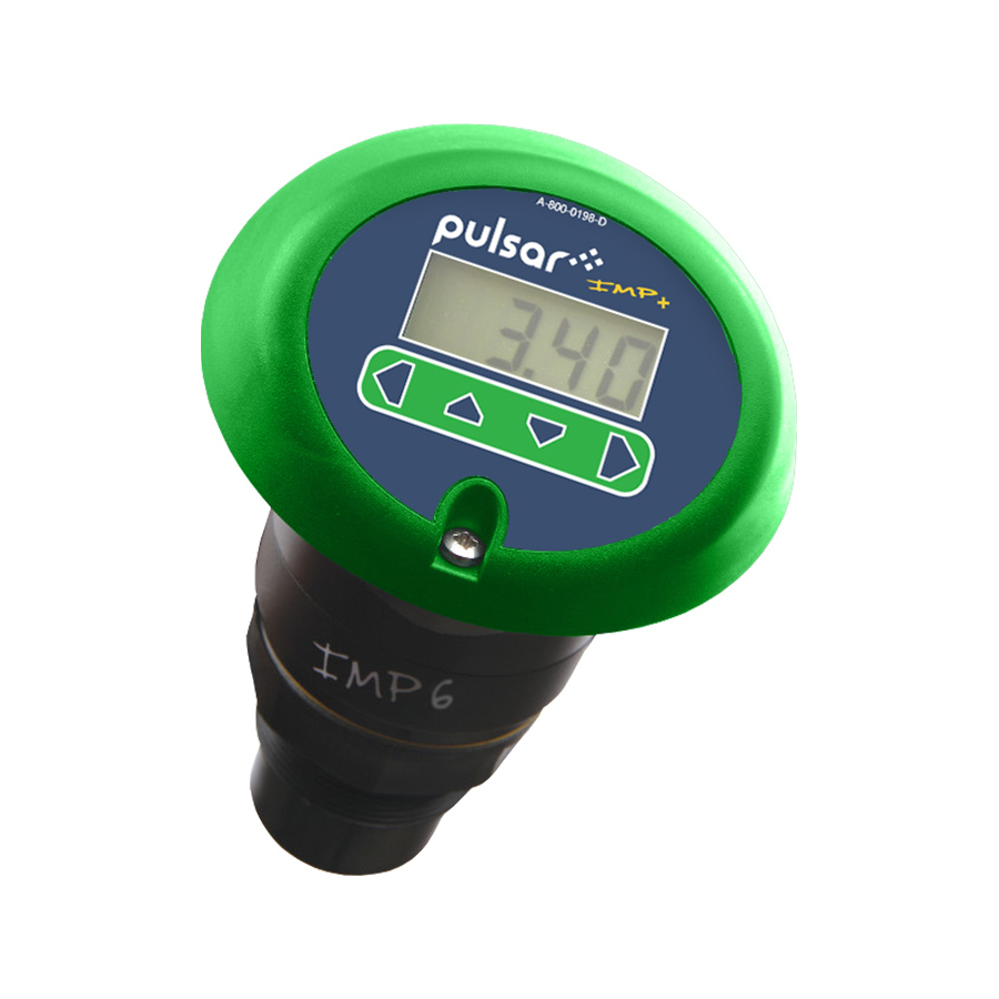
IMP+ INSTRUCTION MANUAL About the IMP+ Functional Description The IMP+ level monitoring system is a highly developed ultrasonic level measurement system which provides non-contacting level measurement for a wide variety of applications in both liquids and solids. Its unique design allows for both 3 wire and 2 wire (loop powered) configuration all within the same unit. -
Page 7: Product Specification
PULSAR MEASUREMENT Product Specification PHYSICAL Dimensions O/A height186mm x O/A diameter 133mm (5.24” x 7.32”) Mounting 1.5” BSP/NPT (IMP3 and 6 models) 2” BSP/NPT (IMP10) Weight Nominal 1 kg Cable entry detail 2 off cable glands 4.5 – 10mm. (torque to 2NM) - Page 8 IMP+ INSTRUCTION MANUAL SUPPLY Power supply 11 - 30V DC Pulsar Measurement operates a policy of constant development and improvement and reserve the right to amend technical details, as necessary.
-
Page 9: Eu Declaration Of Conformity
PULSAR MEASUREMENT EU Declaration of Conformity... -
Page 10: Chapter 2 Installation
If there is any shortage or obvious shipping damage to the equipment, report it immediately to Pulsar Measurement. Power Supply Requirements The IMP+ operates from a DC supply of 11 –30V and will typically draw less than 0.06A. -
Page 11: Dimensions
PULSAR MEASUREMENT Dimensions The dimensions of the IMP+ are shown below: 1” BSP/NPT – IMP+ 3 & 6 2” BSP/NPT – IMP+ 10... - Page 12 IMP+ INSTRUCTION MANUAL Outdoor and Open Vessel Installation The IMP+ can be simply mounted on a bracket, suitable for the application and secured using the thread located at the top of the transducer (2"BSP/NPT). Care should be taken to ensure that the IMP+ is not installed in direct sunlight, to avoid errors in the measurement of ambient temperature.
- Page 13 PULSAR MEASUREMENT Standpipe installations When mounting the IMP+ to a standpipe care should be taken to ensure that the standpipe is of sufficient diameter with reference to its length, see the table below for details: DIA. (D) L = BLANKING...
-
Page 14: Cable Entry
IMP+ INSTRUCTION MANUAL Cable Entry The IMP Lite+ has two M16 cable entries, fitted with a suitable gland, to ensure moisture protection is maintained. Terminal Connection Details The IMP+’s unique design allows for both 3 wire and 2 wire (loop powered) configuration within the same unit the terminal connections for both configurations are as detailed below. -
Page 15: Terminal Connections
PULSAR MEASUREMENT 3 Wire Source mode - the power for the loop is supplied by the IMP+. Terminal Connections 2 Wire Terminal 1 + ve: Direct Current (DC) input (11-30VDC) Terminal 2 - ve: Current Output (4-20mA) - Page 16 IMP+ INSTRUCTION MANUAL Loop Resistance For two wire operation, the maximum cable resistance allowable can be calculated from the graph below. For example, if an IMP+ were supplied from 24v connected as a 2-wire unit (4-20mA only), the maximum total cable resistance is 590 ohms, for a typical 77 ohm /km cable this would mean a maximum cable length of 590/77 = 7.6km, remember this total cable resistance, so this figure has to be divided by 2 to give 3.8km max distance.
-
Page 17: Preparation For Operation
Maintenance There are no user serviceable parts inside your IMP Lite if you experience any problems with the unit, then please contact Pulsar Process Measurement for advice. To clean the equipment, wipe with a damp cloth. Do not use any solvents on... -
Page 18: Chapter 3 How To Use Your Imp
IMP+ INSTRUCTION MANUAL CHAPTER 3 HOW TO USE YOUR IMP+ Operating the Controls Display Whilst in the Run Mode, the 4-digit LCD, by default, will display the current level reading in metres, the display will also alternate between the reading and “LOE”... - Page 19 PULSAR MEASUREMENT Button Functions There are 4 push buttons located under the display. Their name and functions are as follows: BUTTON RUN MODE PROGRAM MODE Used to Navigate out of the Displays details of unit Menu System and return to Serial No.
-
Page 20: Using The Menu System
IMP+ INSTRUCTION MANUAL Using the Menu System The menu system has been designed to make the changing of parameters very simple. Once in the Program Mode the display will show a line of text that displays the menu system. Pressing the Up and Down buttons will scroll the display between the menu items, (as shown below, starting at APP). -
Page 21: Parameter Defaults
PULSAR MEASUREMENT Parameter Defaults Factory Defaults Important Notice When first installing the IMP+, or subsequently moving or using the unit on a new application, before proceeding to program the unit for its intended application it is recommended that you ensure that all parameters are at their default values by completing a Factory Defaults P930, as described in Chapter 5 Parameter Guide. -
Page 22: Chapter 4 Getting Results From Your Imp Lite
IMP+ INSTRUCTION MANUAL CHAPTER 4 GETTING RESULTS FROM YOUR IMP LITE This chapter explains how to use the various functions of your IMP+. Where specific parameters are used, consult Parameter Guide in Chapter 5. Setting up Your Application Empty Distance Empty Distance (P105) is the distance from the face of the transducer to the material at the bottom of the vessel. -
Page 23: Using The Relays
PULSAR MEASUREMENT If the device connected to the mA output is out of calibration, and cannot be calibrated, then the low and high current levels can be trimmed by altering P838 (Low Trim) and P839 (High Trim). To do this, simply enter the value that ensures that 4 mA or 20 mA respectively are shown on the remote device. -
Page 24: Alarm Relay Set-Up
IMP+ INSTRUCTION MANUAL Alarm Relay Set-up The alarm relays are de-energised to turn the alarms “ON” and energised to turn the alarms “OFF”. In this way, loss of power will ensure that the alarm is activated. To set an alarm relay, set the first parameter for the relay to equal 1. For example: Setting Relay 1 for alarm purposes P210 = 1 Setting Relay 2 for alarm purposes P220 = 1... -
Page 25: Control Relay Set-Up
PULSAR MEASUREMENT Control Relay Set-up The control relays are energised to turn the control “ON” (start process function), and de-energised to turn the control “OFF” (stop process function). In this way, loss of power will ensure that the pumps are turned “OFF”. -
Page 26: Loss Of Echo Set-Up
IMP+ INSTRUCTION MANUAL Loss of Echo Set-up When a relay is assigned to Loss of Echo (LOE) or fault condition, it will be set as an alarm relay which will be de-energised to turn the alarm (LOE) “ON” and energise to turn the alarm (LOE) “OFF”. In this way, loss of power will ensure that the alarm is activated. -
Page 27: Resetting Factory Defaults
PULSAR MEASUREMENT Changing the Passcode You can set the passcode to any number from 0000 to 9999. To do this, enter Program Mode and go to SyS1 (System) menu. Select P922 which is the Passcode parameter which can be changed as required. -
Page 28: Using The Rs232 Serial Interface
Using the RS232 Serial Interface The RS232 serial interface is used to communicate between the IMP+, and a PC using the optional Pulsar IMP PC software, this software is used to obtain information from the IMP+ so that echo traces can be viewed, parameters can be uploaded, downloaded, and saved. -
Page 29: Chapter 5 Parameter Listing And Descriptions
PULSAR MEASUREMENT CHAPTER 5 PARAMETER LISTING AND DESCRIPTIONS Parameter Listing This chapter describes all the parameters contained within the IMP+. Application (APP) Menu P100 Mode of Operation This parameter sets the mode of operation, when in run mode, and can be... - Page 30 IMP+ INSTRUCTION MANUAL P106 Span This parameter should be set to the maximum distance from the Empty Level (P105) to the maximum material level. It is automatically set to be equal to the Empty Level (P105) less the Near Blanking distance (P107) when you set the empty level.
-
Page 31: Relay (Rl) Menu
PULSAR MEASUREMENT Relay (rL) Menu P210 (Relay 1), P220 (Relay 2) – Relay Type This parameter defines what type each relay should be, see the table below for available options. OPTION DESCRIPTION 0 = Not in Use (Default) Relay not programmed Relay is programmed as an alarm relay, which will de-energise ON, and energise OFF. - Page 32 IMP+ INSTRUCTION MANUAL P213 (Relay 1), P223 (Relay 2) - Relay “ON” Setpoint This parameter determines the “ON” point for the alarm and should be set as follows, in Measurement Units P104 HIGH ALARM LOW ALARM P213/P223 “ON” Setpoint P213/P223 “ON” Setpoint Higher than Lower than P214/P214 “OFF”...
- Page 33 PULSAR MEASUREMENT P213 (Relay 1), P223 (Relay 2) - Relay “ON” Setpoint This parameter determines the “ON” point for the control relay and should be set as follows, in Measurement Units P104 CONTROL DOWN CONTROL UP P213/P223 “ON” Setpoint P213/P223 “ON” Setpoint...
-
Page 34: Volume (Uol) Menu
IMP+ INSTRUCTION MANUAL Volume (UoL) Menu P600 Vessel Shape This parameter determines which vessel shape is used when utilising “Volume Conversion”. The choices are as shown in the table below, along with the dimensions that are required to be entered (P601-P603). VESSEL SHAPE P600 VALUE DESCRIPTION DIMENSIONS... - Page 35 PULSAR MEASUREMENT VESSEL SHAPE P600 VALUE DESCRIPTION DIMENSIONS Cylinder diameter P600 = 4 Parabola Base and height of bottom P600 = 5 Flat Sloped Base Cylinder diameter Cylinder diameter P600 = Flat Sloped Base and height of bottom Width and breadth...
- Page 36 No dimensions required as level, *P600 =12 Universal curved and volume breakpoints are used *P600 = 11 or 12 can be programmed by IMP PC only. For further assistance please contact your local Pulsar distributor.
- Page 37 PULSAR MEASUREMENT P601-P603 Vessel Dimensions These three parameters are used to enter the dimension required to calculate the volume. The dimensions required are as shown below and are entered Measurements Units (P104). VESSEL SHAPE P601 P602 P603 P600 = 0...
- Page 38 IMP+ INSTRUCTION MANUAL P605 Volume Units This parameter determines the units that you wish to display, for volume conversion. It is used in conjunction with P607 (maximum volume), and the units are shown on the display (subject to P810). The choices are: OPTION DESCRIPTION 0 = No units...
-
Page 39: Display (Disp) Menu
PULSAR MEASUREMENT Display (DiSP) Menu P800 Display Units This parameter determines whether the reading displayed is in Measurement Units (P104), or as a percentage of span. OPTION DESCRIPTION 1 = Measured (Default) Display in Measurement Units (P104) 2 = Percentage... -
Page 40: Ma Output (Loop) Menu
IMP+ INSTRUCTION MANUAL mA Output (LOOP) Menu P834 mA Low Level This parameter sets, in Measurement Units (P104), the value of ‘level’, ‘distance’ or ‘space’, depending on the selected Mode of Operation (P100), at which 4mA will occur. P835 mA High Level This parameter sets, in Measurement Units (P104), the value of ‘level’, ‘distance’... -
Page 41: Compensation (Cop) Menu
PULSAR MEASUREMENT P842 Voltage Output This parameter will determine the range of the voltage output. The voltage output will automatically be scaled to represent the Span P106 where 0volts represents 0% (empty) and maximum voltage 5 or 10 volts, depending on range selected, will represent 100% (full). -
Page 42: P860 Sound Velocity
IMP+ INSTRUCTION MANUAL P860 Sound Velocity This option allows for the velocity of sound to be changed according to the atmosphere the transducer is operating in. By default, the velocity is set for 342.72m/sec which is the speed of sound travelling in air at a temperature of 20 The table below gives details of the velocity of sound in various gaseous atmospheres. -
Page 43: Stability (Sta) Menu
Default = 10.000 metres/minute (32.81 feet/minute) System (SyS1) Menu The following three parameters do not affect how the unit performs, but details, contained in them, may be required, by Pulsar, when making technical enquiries. P921 Enable Code Enables the passcode (P922), which means the passcode must be entered to go into program mode. -
Page 44: Test (Test) Menu
IMP+ INSTRUCTION MANUAL P930 Factory Defaults This parameter resets all parameter values to the original Factory Set values that were installed when the unit was tested before despatch to you. To reset parameters, enter 1 and press ENTER, all parameters, except for the mA trims, will be restored to the factory settings (including the DATEM trace) and on completion Stor (Store) will be displayed after which you can ESC out of this parameter and continue programming the IMP Lite for the required... -
Page 45: Chapter 6 Troubleshooting
PULSAR MEASUREMENT CHAPTER 6 TROUBLESHOOTING This section describes many common symptoms, with suggestions as to what to do. SYMPTOM WHAT TO DO Display blank, transducer Check power supply not firing. No valid echo being received, and unit has gone into fault condition. Check material... -
Page 46: Chapter 7 Disposal
IMP+ INSTRUCTION MANUAL CHAPTER 7 DISPOSAL Incorrect disposal can cause adverse effects to the environment. Dispose of the device components and packaging material in accordance with regional environmental regulations including regulations for electrical \ electronic products. Transducers Remove power, disconnect the Transducer, cut off the electrical cable and dispose of cable and Transducer in accordance with regional environmental regulations for electrical \ electronic products. - Page 47 S U P P O R T @ P U L S A R M E A S U R E M E N T . C O M Copyright © 2020 Pulsar Measurement Ltd. Registered Address: 1 Chamberlain Square CS, Birmingham B3 3AX Registered No.: 3345604 England &...
Need help?
Do you have a question about the IMP+ and is the answer not in the manual?
Questions and answers