
Related Manuals for Hunter ACC


Summary of Contents for Hunter ACC
- Page 1 ACC Controller Owner’s Manual Installation, Programming, and Operating Instructions September 2006 ACC Owner’s Manual Rev E - 9/06 1 of 60...
-
Page 2: Introduction
With plug-in Com and other modules, the ACC can also communicate with a computerized central control system via hardwired cable, radio, dial-up telephone, or cellular modem. ACC is also prewired to accept Hunter wireless remote controls. -
Page 3: Table Of Contents
Connecting the Master Valve(s) and/or Pump Start Relay(s)..............19 Connecting a Rain or Freeze shut off device (optional & not included)............19 Connecting the Hunter Flow Sensor (optional & not included) ..............20 ICR Remote Control............................ 21 Quick Start..............................23 Controller Programming and Operation ...................... -
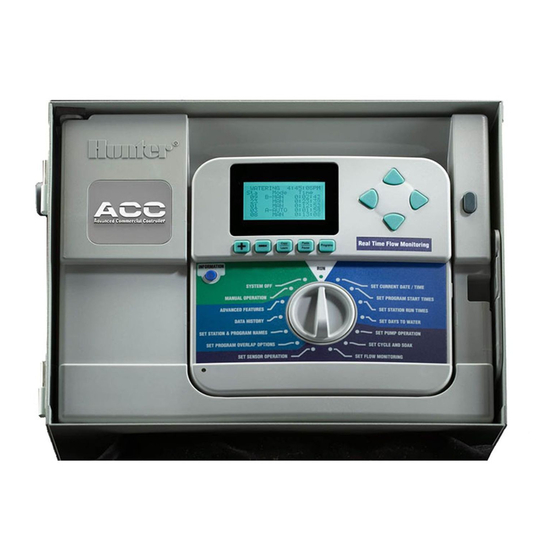
Page 4: Controller Interface & Key Components
A. LCD Display – Backlit, adjustable contrast display (re-lights when any button is pressed). B. + Button – Increases flashing value, depending on function. C. – Button - Decreases flashing value. Most items in ACC screens “wrap” so that you can continue in either direction through all the choices. - Page 5 Also used to access Hidden Features, when held down while turning to specific dial positions. J. Programming Dial – Used to access all functions of ACC. The most basic automatic watering can be set up in the first 4 dial positions.
-
Page 6: Wiring Compartment Interior
L. Earth Ground Lug – for connection of earth ground copper wire (for surge protection only). Do not connect valve commons – see Master Module for Common wiring of solenoids and valves. ACC Owner’s Manual Rev E - 9/06 6 of 60... -
Page 7: Explanation Of Symbols
Shaded or partially shaded areas are preferable to prolonged direct Facepack Door sunlight. The ACC controller is relatively heavy, about 30lbs/13.6 kg in t Positioning Hanger metal wall mount configuration. Mounting includes a posi tioning hanger to assist with installation. -
Page 8: Connecting Ac Main Power, Wall Mount Cabinet
(3”/75mm) with magnetic tip to install the remaining 3 screws, one at each anchor position, and secure. Connecting AC Main Power, Wall mount cabinet The ACC can operate with either 120VAC or 230VAC power, depending on how the incoming AC wires are connected. Supply wires must be 14AWG (1.85mm) or larger. -
Page 9: Metal Cabinet, Optional Pedestal Installation
The 120V~ ground wire (bare, or green) is not used in ACC transformer connections. The service ground wire may be connected to earth ground if required. Tighten screw and replace cover. For 230V~ operation, connect the incoming power wire (hot, brown in many wiring standards) to align in the wiring block with the brown wire lead from the transformer. -
Page 10: Connecting The Metal Pedestal Main Ac Power
Secure the pedestal to the bolts using the enclosed washers and nuts. 5. Remove the door and faceplate of the ACC and attach the metal cabinet of the ACC to the top of the pedestal using the ½”/13mm and 2”/50mm metal conduit nuts in the pedestal. Tighten securely by engaging teeth with a screwdriver and tapping in a clockwise direction. -
Page 11: Connecting Plastic Pedestal Ac Main Power
Insert the two 120/230~ power wires through the AC power conduit (keep power wires separate from low voltage and communication wires) and route into the wiring compartment. The ACC pedestal has a separate wiring junction box below the Junction main transformer assembly. All 120/230~ connections are made in this junction box. - Page 12 Brown wire in the upper terminal block. Insert the stripped wire and tighten screw securely. Replace cover, apply AC power, and test. Refer to Earth Ground and Station Wiring sections for additional connections. ACC Owner’s Manual Rev E - 9/06 12 of 60...
-
Page 13: Connecting Earth Ground
Connecting Earth Ground (all configurations) The ACC features a copper earth ground lug, to the immediate right of the transformer assembly. This earth ground connection is isolated from the primary AC power and is used to ground incoming surges from the communications and output valve wires. This connection can be used to ground the primary AC power. - Page 14 1. ACM600, 6-station output module with surge suppression and diagnostic LEDs. 2. AGM600, 6-station output module with heavy-duty surge suppression and diagnostic LEDs. These two types of modules may be mixed within the same installation, if desired. ACC Owner’s Manual Rev E 9/06 14 of 60...
- Page 15 One of the LEDs will illuminate red briefly, to show that the new module has been recognized. ACC Owner’s Manual Rev E 9/06 15 of 60...
-
Page 16: Connecting The Valve Wires
Each station output is rated for .56 A, max, or enough to operate two typical Hunter solenoids simultaneously. Once the output module is installed in the slot, the station numbers assigned to the output module appear in the upper deck label above each slot. -
Page 17: Connecting Decoder Output Path Wires
You may use any number of paths to reach all 99 stations. Each path should consist of Hunter Industries Model IDWIRE1 or IDWIRE2 color-coded decoder wire. This is a twisted, solid-core wire suitable for direct burial, and is always color- coded red and blue. -
Page 18: Vac Test Terminal (Constant 24V)
E. 24VAC: Always-on 24V test terminal, for locating valves in the field. Can also be used to power low-draw sensor receivers such as Hunter WRC. F. Flow Sensor connections (+ and -): connections for Hunter HFS flow sensor. G. ET connections (+ and -): Not used. -
Page 19: Connecting The Master Valve(S) And/Or Pump Start Relay(S)
Programming and Operations portion of this manual. Connecting a Rain or Freeze shut off device (optional & not included) Up to 4 Hunter Clik™ sensors can be connected to the ACC controller, including: • Mini-Clik • Rain-Clik (including Wireless Rain Clik) •... -
Page 20: Connecting The Hunter Flow Sensor (Optional & Not Included)
Operation section of Programming and Operations. • Connecting the ET Module (optional & not included) To connect a Hunter ET System to the ACC controller, use the adapter supplied with the ET System made especially for ACC. The adapter has SmartPort pins to align with the SmartPort plug on the upper left of the controller. -
Page 21: Icr Remote Control
• To connect a Hunter HFS Flow Sensor, route the pair of 18AWG (1mm) wires from the sensor into the cabinet through one of the low voltage conduit openings in the bottom of the enclosure. • Locate the “Flow” red and black coded terminals near the left side of the Master Module. - Page 22 Remote starts are followed by “ICR” in the display. To set up an ICR remote control for operations with ACC, consult the ICR instructions. Use the Mode button on the ICR transmitter to select a station size of “240” to allow access to all ACC programs and stations.
-
Page 23: Quick Start
The ACC’s real time clock is independent of external power or the 9VDC battery, and will keep time during a power failure of virtually any length. When external power is restored, the ACC will still have the correct time and will be ready to irrigate. - Page 24 (hh:mm:ss format, from 1 second to 6 hours). Turn the dial back to the Run position, and the station will start within a few seconds. ACC Owner’s Manual Rev E 9/06 24 of 60...
-
Page 25: Controller Programming And Operation
Programming these hidden features is explained in the Hidden Features section. The ACC has the following Hidden Features: No Water Window... -
Page 26: Setting Program Start Times
Stacking). All six programs can be programmed to Overlap and thus potentially run simultaneously. This is great when a short watering window is necessary and the hydraulics of the system allows for high total water flow. ACC Owner’s Manual Rev E 9/06 26 of 60... -
Page 27: Setting Station Run Time Duration
PROGRAM A PROG A SEAS ADJ 100% • Seasonal Adjust value for the Program • Hidden Feature: Timed Delay between _____________________________ Stations STATION 01 PROGRAMMED ACTUAL Setting Station watering duration 0:00:00 0:00:00 ACC Owner’s Manual Rev E 9/06 27 of 60... -
Page 28: Changing Seasonal Adjust
+ and – buttons to change the value to GLBL. GLBL is located between the 101 and 100% positions. Timed Delay between Stations • Programming this feature is explained in the Hidden Features section. Setting Days to Water ACC Owner’s Manual Rev E 9/06 28 of 60... - Page 29 WATER ON ODD DAYS and press the + button. The “-“ will disappear, TUE WED THU and the day will be available for Interval watering again. SAT SUN Odd/Even Watering ACC Owner’s Manual Rev E 9/06 29 of 60...
-
Page 30: Setting Pump And Master Valve Operation
(H:MM) Setting Station Cycle and Soak durations • Turn the dial to the SET CYCLE AND SOAK 0:01 0:01 position • Press the up or down arrow keys to change stations ACC Owner’s Manual Rev E 9/06 30 of 60... -
Page 31: Setting Flow Monitoring
Hunter Flow Sensor (HFS) or a Data STATION 01 Industrial flow sensor is required for this feature to FLOW LMT DELAY function. The ACC must first learn the normal flow, (GPM) (M:SS) by station, for flow sensing to operate correctly. NOT LEARNED Step 1: Select the flow sensor •... - Page 32 Step 3: Preparing for Flow Learning • ACC will only learn flows for stations which have run times in Automatic Programs. Verify that each station has a run time in an Automatic Program (A through F).
- Page 33 Are you SURE? you to confirm that you want to begin ‘+’ =YES : ‘-‘ =NO watering to learn flow. • The ACC will begin watering at the lowest 6:46:04 AM station number to learn its typical flow. MONDAY 3/07/06...
-
Page 34: Flow Alarms
Flow Alarms Once station flow has been learned, ACC will always compare actual flow from the flow meter to the learned flow (even when multiple stations are running). When the actual flow exceeds the limit over learned flow, after the specified delay has elapsed, an alarm will occur. -
Page 35: Alarm Logs (Also See Historical Data/Data History Section)
(Over or Under). Tips on Flow Alarms: • There is only one flow meter per ACC controller, and controllers do not share information with one another. If a controller with a meter “sees” flow caused by another controller, drawing water from the same point of connection to the water supply, the controller will experience many false alarms, because it cannot account for the flow. -
Page 36: Setting Clik™ Sensor Operation
Setting Clik™ Sensor Operation The ACC is capable of monitoring four individual Clik-type sensors, in addition to the flow sensor. Typically these sensors are weather-related SENSOR OPERATION sensors such as the Mini-Clik™... -
Page 37: Sensor Alarms
0:00:36 Sensor alarms have no effect on the Test program. 1-CUST 0:01:30 All of these types of programs are initiated by a human operator so the sensor settings do not apply. ACC Owner’s Manual Rev E 9/06 37 of 60... -
Page 38: Setting Program Overlap Options
Once the Program Overlap Option has been selected for the controller, individual programs can be set to Overlap or Stack at the Set Program Start Times position. Option One: Stack or Overlap ACC Owner’s Manual Rev E 9/06 38 of 60... -
Page 39: Option Two: Smartstack
Stack only after When using SSGs, the controller can electrically 2 stations and only handle one SSG, two stations, and two Master an SSG are running. Valves simultaneously, maximum. You must ACC Owner’s Manual Rev E 9/06 39 of 60... -
Page 40: Setting Station & Program Names
Setting Station & Program Names All stations and programs of the ACC can be named for easy reference. This can either be setup via the IMMS central control software, or it can be programmed at the controller using the keypad. -
Page 41: Historical Data/Data History
Select total to view alarm logs. CONTROLLER Flow totals can be viewed for: TODAY • The entire controller • An individual program (projected flow) YESTERDAY • An individual SSG • Or an individual station. ACC Owner’s Manual Rev E 9/06 41 of 60... -
Page 42: Common Fault Messages
“doubled” on an ACC output. A solenoid with a holding current of .3 A is acceptable, but two of them (equaling .6 A) would exceed the .56 A max limit and cause an Overcurrent. -
Page 43: Hidden Features
Overflow: A station has exceeded its learned flow upper limit during irrigation. ACC totals the upper limit of the learned flow for all running stations, and compares them to the actual flow at the flow meter. When the combination of stations exceeds the total upper limits (after all Delay times have elapsed), the controller will Pause and go into alarm diagnostic mode. -
Page 44: Delay Between Stations Information+Set Station Run Times
In the ACC, Delay Between Stations can be set by Program, which can be very useful when only certain types of stations (large rotor zones, low flow drip) are grouped within a program. -
Page 45: Setting The Flow Sensor Size And Type (Information+Set Flow Monitoring)
Setting the Flow Sensor size and type (INFORMATION+Set Flow Monitoring) ACC’s Real Time Flow Monitoring is designed to work with Hunter HFS flow sensors. It is necessary to tell ACC what size fitting the HFS has been installed into, so that flow can be measured accurately for pipe size. -
Page 46: Ssg (Simultaneous Station Group) Setup (Information+Overlap)
They can also be named, to make using them easier. SSGs are not required to operate the ACC controller. They are a valuable extra feature for advanced users. See the SSG Rules after these programming instructions for additional information. - Page 47 Changing or deleting an existing SSG is done from the same Hidden Feature. Hold down the Information button, and turn the dial back to the Set Program Overlap Options position. Release the Information button to view the SSG Setup screen. ACC Owner’s Manual Rev E 9/06 47 of 60...
-
Page 48: Custom Manual Program Setup (Information + Manual Operation)
Use the + button to advance through all existing SSGs, until the next unused SSG appears (having all dashed lines with no station selections), and select stations as desired. Once the controller is in ACC Setup mode, all 20 SSGs are available, whether they are used or not. -
Page 49: To Start A Custom Manual
Test Program: Programs button (hold) ACC has a quick Test program which will run all stations for a selectable period of time, in numerical order. The Test is an easy way to walk through every station in the system to verify ACC Owner’s Manual Rev E... -
Page 50: Easy Retrieve™ Backup (Information + Programs Button At Run Position)
To save an Easy Retrieve backup: First, make sure the controller is in the desired state of programming, including Days to Water, Start Times, Run Times, names, etc. Turn the dial to the Run position. ACC Owner’s Manual Rev E 9/06 50 of 60... -
Page 51: Manual Operations
Manually Start Station 01…”, but this only indicates that it will start at the beginning of the program. Each station will run for its programmed time (including Cycle and Soak settings), and stations with no run time in the selected program will be skipped. ACC Owner’s Manual Rev E 9/06 51 of 60... -
Page 52: System Off
The display at the Run position will then show the number of days for the Off setting. This display will count down each day, showing the remaining days until automatic irrigation will resume. ACC Owner’s Manual Rev E 9/06 52 of 60... -
Page 53: Reset
Reset The ACC controller can be reset, erasing most programmed information. There are 5 different levels of Reset command available, but once any of them is chosen, the information will be permanently erased. These operations are not reversible! Reset should only be performed if: a) a “clean start”... -
Page 54: Status Lights (Adm-99 Output Module)
Each decoder is programmed with station address(es) at the controller, before installing it in the 2-wire path. The decoder output module has two holes in the lower right called “Programming Port”. Program the station number(s) into the decoders, and then write the station ACC Owner’s Manual Rev E 9/06 54 of 60... - Page 55 4. Turn the controller dial to the Advanced Features POWER FACTOR: position. INRUSH: 5. The display will show “DECODER FUNCTIONS”. Press the + button to select. (The other functions are Press PRG to send. ACC Owner’s Manual Rev E 9/06 55 of 60...
- Page 56 Decoders may be reprogrammed at any time. If it is necessary to change the station numbers or other settings of a previously programmed decoder, the decoder may be reconnected to the ACC Owner’s Manual Rev E 9/06 56 of 60...
-
Page 57: Decoder Pump/Master Valves
It is possible to use the 200, 400, or 600 as a P/M output, but the other outputs will not function. • The ACC or AGC controller only supports 2 Pump/Master Valve outputs, total, regardless of how they are connected. There are two “hardwired” output terminals on the controller’s Master Module (P/M1 and P/M2). -
Page 58: Troubleshooting
No station light, or red light: Swap with known-good module, check for green light. If new module works, replace old module (probably surge overload). If new known-good ACC Owner’s Manual Rev E 9/06 58 of 60... -
Page 59: Specifications
Pump/Master Valve output: 325mA @24 VAC 24 VAC Test terminal output: 300mA @ 24 VAC Solenoid capacity: 2 standard 24 VAC Hunter solenoids per output, 14 solenoids max simultaneous (includes dual P/MV outputs). Battery, facepack: 9VDC alkaline, for facepack remote power only. - Page 60 ACC Owner’s Manual Rev E Hunter Industries Incorporated• The Irrigation Innovators 1940 Diamond Street • San Marcos, CA 92078 • TEL: 1 (760) 744-5240 • FAX: 1 (760) 744-7461 www.HunterIndustries.com 9/06...
Need help?
Do you have a question about the ACC and is the answer not in the manual?
Questions and answers