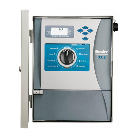
Hunter ICC2 Owner's Manual
Modular residential and commercial irrigation controller
Hide thumbs
Also See for ICC2:
- User manual ,
- Owner's manual (36 pages) ,
- Programming instructions (2 pages)
Table of Contents
Advertisement
ICC2
MODULAR RESIDENTIAL AND COMMERCIAL
IRRIGATION CONTROLLER
Owner's Manual
•
I2C-800-PL: 8-station base model, expandable to 38 stations, plastic outdoor cabinet
•
I2C-800-M: 8-station base model, expandable to 54 stations, gray metal outdoor cabinet
•
I2C-800-SS: 8-station base model, expandable to 54 stations, stainless steel outdoor cabinet
•
I2C-800-PP: 8-station base model, expandable to 54 stations, plastic pedestal
System O
Manual
Solar Sync
®
Seasonal Adjust
Date/Time
Start Times
Run Times
Water Days
Advertisement
Table of Contents

Related Manuals for Hunter ICC2


Summary of Contents for Hunter ICC2
- Page 1 ICC2 MODULAR RESIDENTIAL AND COMMERCIAL IRRIGATION CONTROLLER System O Date/Time Manual Start Times Run Times Solar Sync ® Water Days Seasonal Adjust Owner’s Manual • I2C-800-PL: 8-station base model, expandable to 38 stations, plastic outdoor cabinet • I2C-800-M: 8-station base model, expandable to 54 stations, gray metal outdoor cabinet •...
- Page 2 FORWARD DESIGN. BACKWARD COMPATIBLE. System O Date/Time Start Times Manual Run Times Solar Sync ® Seasonal Adjust Water Days hunter.direct/ICC2help...
-
Page 3: Table Of Contents
Connecting a Master Valve (Optional) ....18 Connecting a Pump Start Relay (Optional) ..19 Connecting a Hunter Clik Sensor ....20 Sensor Bypass Switch ........20 Connecting a Hunter Solar Sync Sensor (Not Included) ..............21 Wired Solar Sync Installation ......21 Wireless Solar Sync Installation ......21... -
Page 4: Specifications
Width: 11.5" (29.2 cm) DEFAULT SETTINGS • Depth: 5" (12.7 cm) • All stations are set to zero run time. This controller has a non-volatile memory that retains all entered program data even during power outages, without the need for a battery. hunter.direct/ICC2help... -
Page 5: Icc2 Components
Program Indicators: Identifies the program in use (A, B, C, or D). ③ ➒ Water Days Symbol: Choose desired watering days. ➓ Solar Sync Symbol: Indicates optional Hunter Solar Sync sensor is in use. ④ ⓫ Days of the Week: Monday–Sunday. ⑤... -
Page 6: Control Dial
Run Times Solar Sync ® Seasonal Adjust: Change all run times in all programs by a percentage (5% to 300%). Seasonal Adjust Water Days Solar Sync®: Set up and adjust option for Hunter Solar Sync sensor. ➑ ➐ ⑥ ⑤ ④... -
Page 7: Wiring Compartment
Power Module: Provides power to the controller and must be in place for controller to operate; contains 24 VAC, ⑥ sensor, remote, and P/MV terminals. SmartPort Connector: Enables use of Hunter ROAM and ➑ ROAM-XL remotes. ⑤ Transformer: Pre-installed with 120 VAC, 230 VAC, neutral, ➐... -
Page 8: Mounting The Controller
Drill four pilot holes for the remaining mounting screws. Secure the controller in place by installing screws in the four remaining holes from inside the cabinet. Re-attach the control panel and the door. Wall Mounting, plastic box.2 Wall Mounting, plastic box.2 hunter.direct/ICC2help... -
Page 9: Metal Cabinet Wall Mounting
Mounting the Controller Wall Mounting METAL CABINET WALL MOUNTING Remove door and control panel for easier access. Use the enclosed hole template to mark and drill mounting holes. Be sure to leave enough room to open the door. Install screw anchors if attaching to drywall or masonry wall. Secure a 1"... -
Page 10: Metal Pedestal Mounting
Lock ⑥ Pedestal Mounting J-Bolt (qty: 4) Nut, Hex 3/8" (qty: 8) Washer, Flat 3/8" (qty: 8) 2" Conduit Nipple 2" Conduit Locknut Hex Nut, Door Lock 1/2" Conduit Coupler 1/2" Conduit Nipple ② ① ③ ➒ ➑ ➐ hunter.direct/ICC2help... -
Page 11: Prepare The Concrete
Mounting the Controller PREPARE THE CONCRETE PLASTIC PEDESTAL MOUNTING Prepare a form for a concrete pad, approximately 20" W x 16" D x 4" H (50 cm W x 40 cm D x 10 cm H) at grade Mount the irrigation controller pedestal to the level. -
Page 12: Connecting Ac Power
Turn off AC power at the source and verify it is off. Disconnect the facepack ribbon cable, and remove the facepack from the cabinet. Remove the screw and wiring compartment cover from the front of the transformer junction box. Wiring Controller Power Wiring Controller Power hunter.direct/ICC2help... -
Page 13: 120 Vac Wire Nut
Connecting AC Power 120 VAC WIRE NUT 120 VAC TERMINAL BLOCK Wiring Controller Power, 120V - Wire block Wiring Controller Power, 120V-Wire nut Brown Wire Black Wire Blue Wire Green Wire (230 Volt) (120 Volt) (Neutral) (Ground) Brown Wire (230 Volt) Black Wire (120 Volt) Blue Wire (Neutral) Green Wire (Ground) -
Page 14: Battery Activation
Optional 9-volt battery (not included) may be used only to program the control panel when removed from cabinet, and is not capable of running automatic schedules or activating stations. Re-install cover plate to enclose battery compartment. ③ ④ ⑤ hunter.direct/ICC2help... -
Page 15: Installing Modules
Installing Modules To add a station output module Installing Modules ① ② Flip the blue locking lever into the vertical (unlocked) position. Tip the two tabs on one end of the module into the mating holes in one end of the slot, and tip the module firmly into place. -
Page 16: Power Modules
SmartPort™ connector for use with Hunter ROAM and/or ➐ ROAM XL remotes. 24VAC (x2) Transformer Connection: Connects 24 VAC yellow wires from transformer. Also used to power Hunter ➑ sensor modules and receivers. ➒ GND: Connects green safety ground wire from Station Modules (ICM-800 shown) ⑩... - Page 17 Installing Modules The ICM2200 expansion module increases overall station count to 38 (plastic) and 54 (metal). This module can be installed exactly like the ICM400 and ICM800 station modules; however, it covers two station output slots. Note: The ICM2200 must be installed in the highest two output slots: 3 and 4 (plastic) or 5 and 6 (metal).
-
Page 18: Installation Instructions
Installation Instructions CONNECTING A MASTER VALVE (OPTIONAL) CONNECTING STATION WIRES Each ICC2 controller is supplied with a factory-installed base Complete this section only if you have a Master Valve installed. The ICC2 has one Pump/Master Valve (P/MV) module for up to 8 stations (ICM-800). Multiple additional... -
Page 19: Connecting A Pump Start Relay (Optional)
The P/MV output is located on the power output module, in the upper left corner of the ICC2. Hunter Pump Start Relays come with two yellow 24 VAC flying leads, one of which will connect to the common “COM” terminal and the other to the P/MV terminal. -
Page 20: Connecting A Hunter Clik Sensor
All Hunter Clik sensors are normally closed, and open on alarm, which alerts the controller to suspend watering. The ICC2 can be programmed to shut down the entire controller, or only individual stations, once the sensor is triggered (see Programmable Sensor Override instructions). -
Page 21: Connecting A Hunter Solar Sync Sensor (Not Included)
The LED on the receiver will blink four ICC2 has the Solar Sync software built in to the controller, times and then turn off, indicating that the signal from the sensor has been acknowledged. -
Page 22: Connecting A Hunter Remote (Not Included)
Installation Instructions CONNECTING A HUNTER REMOTE (NOT INCLUDED) The ICC2 is compatible with both Hunter ROAM and ROAM XL remotes, and each controller comes with a factory- installed SmartPort. This provides instant remote connection capability, which allows for manual operation of your system without having to walk back and forth from the controller. -
Page 23: Programming The Controller
Programming the Controller Programming the Controller SETTING CURRENT DATE AND TIME Turn the dial to the Date/Time position. The current year will be flashing. Use the + and – buttons to change the year. Press the ► button to proceed to setting the month. -
Page 24: Setting Station Run Times
2nd, 4th, 6th, etc.). Press the ► button past all days of the week so the pointer is blinking above “ODD” or “EVEN.” Press the + button to select or the – button to cancel Odd or Even days. hunter.direct/ICC2help... -
Page 25: Selecting Interval Watering
Programming the Controller SELECTING INTERVAL WATERING This feature is convenient if you want to have a more consistent watering schedule without having to worry about specific dates or days of the week. The interval number represents the actual interval of days during which watering will occur. -
Page 26: Selecting Pump/Master Valve Activation
Turn the dial to the Seasonal Adjust position. Press the + or – buttons to change from 5% up to 300% of original run times. Note: The default setting for Seasonal Adjust is 100%. hunter.direct/ICC2help... -
Page 27: Setting Solar Sync
Programming the Controller SETTING SOLAR SYNC Add an optional Solar Sync sensor (wired or wireless) for automatic Seasonal Adjustment based on daily weather conditions on-site. Turn the dial to the Solar Sync position. The Region setting will be blinking. Press the + or – buttons to select Region 1–4. -
Page 28: Setting System Off
Note: To cancel Programmable Rain Off settings, turn the dial to the System Off position, wait for the “OFF” to stop blinking, and turn the dial back to the Run position. hunter.direct/ICC2help... -
Page 29: Hidden And Advanced Features
Then, the program will revert to station 1 and complete its remaining cycle and soak schedule. ICC2 allows the user to program the controller so a sensor To access the Cycle and Soak menu, with the dial in the response is independent from station to station. -
Page 30: Delay Between Stations
SOLAR SYNC DELAY This feature allows the user to program a delay between ICC2 with built-in Solar Sync programming has the ability to station activation and shutoff. This is particularly helpful on delay the automatic, daily update of the Seasonal Adjustment systems with slow-closing valves, pumps that are operating value from Solar Sync for up to 99 days. -
Page 31: Clik Delay
Note: An active Clik Delay can be canceled at any time by simply turning the dial to the System Off position, waiting ICC2 is capable of saving the preferred watering program into for “OFF” to stop blinking, and returning the dial to the Run memory for retrieval at a later time. -
Page 32: Total Reset
RUN PROGRAM (ONE-TOUCH MANUAL START) The Total Reset feature will erase all of the controller’s ICC2 is also capable of activating an entire program without memory and set everything back to factory presets. Once you using the dial. This option is great for a quick cycle when extra... -
Page 33: Troubleshooting
Hidden and Advanced Features Troubleshooting Symptom Possible Cause Solution Display shows a station number Faulty station solenoid or short in Check field wiring and solenoids for continuity, with "ERR" the field wiring and replace any faulty solenoids. Check the master valve or pump start wires for Short in the pump start/master valve continuity, and replace or repair any shorted Display shows "P ERR"... -
Page 34: Compliance Information
RSS standard(s). Operation is subject to the following Hunter Industries declares that the irrigation controller Model two conditions: ICC2 complies with the standards of the European Directives of “electromagnetic compatibility” 2014/30/EU and “low (1) this device may not cause interference, and voltage”... - Page 35 Notes Built on Innovation Built on Innovation ® ®...
- Page 36 Helping our customers succeed is what drives us. While our passion for innovation and engineering is built into everything we do, it is our commitment to exceptional support that we hope will keep you in the Hunter family of customers for years to come. Gregory R. Hunter, CEO of Hunter Industries hunter.direct/icc2help...
Need help?
Do you have a question about the ICC2 and is the answer not in the manual?
Questions and answers
how do i no reset with no reset ? i have a hunter icc2
To reset a Hunter ICC2 without using the reset function, you can manually clear all programmed data. Since the default setting has all stations set to zero run time, you can:
1. Set all station run times to zero.
2. Clear all start times.
3. Remove all days assigned for watering.
4. Adjust any other settings (like sensor overrides or delays) to default or inactive states.
This will effectively return the controller to a default-like state without using a formal reset.
This answer is automatically generated