Table of Contents
Advertisement
Quick Links
Advertisement
Table of Contents

Related Manuals for AEMC F01


Summary of Contents for AEMC F01
- Page 1 CLAMP MULTIMETER E N G L I S H User Manual...
- Page 2 The recommended calibration interval for this instrument is 12 months and begins on the date of receipt by the customer. For recalibration, please use our calibration services. Refer to our repair and calibration section at www.aemc.com. Serial #: ________________________________ Catalog #: 2129.51 Model #:...
-
Page 3: Table Of Contents
1.1 International Electrical Symbols ..........3 1.2 Definition of Measurement Categories ........4 1.3 Receiving Your Shipment ............4 1.4 Ordering Information ..............4 1.4.1 Accessories and Replacement Parts ......4 2. PRODUCT FEATURES ..............5 2.1 Description ................5 2.2 Model F01 Control Functions ............6 2.3 Rotary Switch Functions ............6 2.4 Hold Button Primary Functions ..........7 2.5 Hold Button Secondary Functions (with rotary switch) ....7 2.5.1 Disable Auto-Off Function ..........7 2.5.2 Activate The V-Live Function ........7 2.5.3 Displaying The Internal Software Version ....7... - Page 4 4. OPERATION .................. 15 4.1 Voltage Measurement - ( ) ..........15 4.2 Audio Continuity Test and Resistance Measurement .....15 4.5 Current Measurements - ( ) ..........16 5. MAINTENANCE ................17 5.1 Changing the Battery ..............17 5.2 Cleaning ..................17 5.3 Storage ...................17 Clamp-on Multimeter Model F01...
-
Page 5: Introduction
Risk of electric shock. The voltage at the parts marked with this symbol may be dangerous. This symbol refers to a type A current sensor. This symbol signifies that application around and removal from HAZARDOUS LIVE conductors is permitted. In conformity with WEEE 2002/96/EC Clamp-on Multimeter Model F01... -
Page 6: Definition Of Measurement Categories
Ordering Information Clamp-on Multimeter Model F01 ........Cat. #2129.51 Includes multimeter, set of red and black leads with probe tips, 9V battery, carrying pouch and this user manual. 1.4.1 Accessories and Replacement Parts Replacement set of leads, red and black with probe tips ..Cat. #2118.92 General Canvas Pouch (4.25 x 8.5 x 2") ...... -
Page 7: Product Features
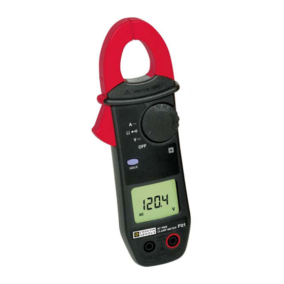
CHAPTER 2 PRODUCT FEATURES Description The Clamp-on Multimeter, Model F01 emphasizes reliability and simplicity of use to respond to the needs of power professionals. Features: A compact unit, integrating the current sensor for intensity measurements without breaking the test circuit Outstanding ergonomic features: ● automatic selection of AC or DC measurement - V only ● automatic selection of measurement ranges ● programmable audio voltage indication (V-Live) ● “over-range” indication ● power auto-off Compliance with IEC electrical safety standards and CE markings Light and rugged construction for field use Clamp-on Multimeter Model F01... -
Page 8: Model F01 Control Functions
Model F01 Control Functions Jaws Command Buttons 4-way Rotary Switch Liquid Crystal Display Rotary Switch Functions OFF Deactivation of the clamp, activation is ensured by selection of other functions DC and AC voltage measurement (rms value) Continuity and resistance measurement AC ampere measurement (rms value) Clamp-on Multimeter Model F01... -
Page 9: Hold Button Primary Functions
Displaying The Internal Software Version While pressing down the HOLD button, bring the rotary switch from the OFF position to the A position. The unit beeps, the software version is displayed in the form UX.XX for 2 seconds, then all the segments of the display are shown. Clamp-on Multimeter Model F01... -
Page 10: Liquid Crystal Display
The liquid crystal display includes the digital display of the measured values, the related units and symbols. 2.6.1 Digital Display 4 digits, 9999 counts, 3 decimal points, + and - signs (DC measurement) + OL : Positive value range exceedance (>3999cts) - OL : Negative value range exceedance OL : Unsigned value range exceedance - - - - : Indeterminate value (middle segments) 2.6.2 Symbol Display HOLD Function active Constant operation (no power auto-off) Flashing: V-Live function selected Fixed: Continuity measurement Measurement in AC mode Measurement in DC mode Flashing: power limited to approximately 1 hour Fixed: battery drained, operation and accuracy are no longer guaranteed Clamp-on Multimeter Model F01... -
Page 11: Buzzer
Buzzer Different sounds are emitted according to the function performed: • Short and medium sound: valid button • Short and medium sound every 400 ms: voltage measured is higher than the unit’s guaranteed safety voltage • 5 short and medium recurring sounds: automatic deactivation of the instrument • Continuous medium sound: continuity value measured below 40Ω • Modulated medium continuous sound: value measured in volts, higher than 45V peak when the V-Live function is selected Clamp-on Multimeter Model F01... -
Page 12: Specifications
**In AC if the value of the voltage measured is <0.15V the display indicates 0.00. 3.2.2 Audio Continuity ( ) / Resistance Measurement (Ω) Range 400Ω Measuring Range 0.0 to 399.9Ω Accuracy* 1% of Reading + 2cts Resolution 0.1Ω Open Circuit Voltage ≤3.2V Measuring Current 320µA Overload Protection 500V or 750V or peak *with compensation for measurement lead resistance Clamp-on Multimeter Model F01... -
Page 13: Current (A)
**In AC, if the value of the current measured is <0.15A, the display shows 0.00. Battery: 9V alkaline battery (type IEC 6LF22, 6LR61 or NEDA 1604) Battery Life: 100 hrs approx Auto-off: After 10 minutes of no activity Mechanical Specifications 1. Reference Range Temperature: 2. Operating Range 3. Storage Range (without battery) Œ Ž Ž Temperature in °C Operating Temperature: 32 to 122°F (0 to 50°C); 90% RH Storage Temperature: -40 to 158°F (-40 to 70°C); 90% RH Altitude: Operation: ≤2000m Storage: ≤12,000m Dimensions: 2.76 x 7.6 x 1.46" (70 x 193 x 37mm) Weight: 9.17 oz (260g) Clamp Tightening Capacity: ≤1.00” (≤26mm) Clamp-on Multimeter Model F01... -
Page 14: Safety Specifications
Electrostatic discharges: 4kV on contact, aptitude criterion B 8kV in the air, aptitude criterion B • Radiated field: 10V/m, aptitude criterion B • Fast Transients: 1kV, aptitude criterion B • Conduit interference: 3V, aptitude criterion A Mechanical Resistance • Free fall 1m (test as per IEC 68-2-32) • Impact: 0.5 J (test as per IEC 68-2-27) • Vibration: 0.75mm (test as per IEC 68-2-6) Auto-extinction (per UL94) • Housing V0 • Jaws V0 • Display window V2 Clamp-on Multimeter Model F01... -
Page 15: Variations In Operating Range
40 dB mode in DC Rejection of series 0 to 600V <1ct 60 dB mode in AC 0 to 400A <1ct 60 dB Rejection of common <1ct 60 dB 0 to 600V/50Hz mode 0.08A/100V 0.12A/100V Influence of external 0 to 400A/m 85 dB 60 dB magnetic field (50Hz) Number of jaw open- 50000 0.1% R 0.2% R + 1ct ing movements Clamp-on Multimeter Model F01... -
Page 16: Typical Frequency Response Curves
Typical Frequency Response Curves - V = f (f) Specified limits -10% -12% 10000 Hz 100 Hz 10 Hz 1000 Hz Frequency (Hz) - I = f (f) Specified limits 10 Hz 100 Hz 1000 Hz 10000 Hz Frequency (Hz) Clamp-on Multimeter Model F01... -
Page 17: Operation
§ 2.6.2). For voltages ≥600V or rms, a repetitive beep indicates that the measured voltage is higher than the acceptable safety voltage (OL). Audio Continuity Test - ( ) and Resistance Measurement - (Ω) 1. Connect the measurement leads to the terminals. 2. Set the rotary switch to the “ ” position. 3. Connect the unit to the circuit to be tested. The buzzer is contin- uously active as soon as contact is established (circuit closed) and if the resistance value measured is less than 40Ω. NOTE: Above 400Ω, the display indicates OL. Clamp-on Multimeter Model F01... -
Page 18: Current Measurements - ( )
Current Measurements - ( 1. Set the rotary switch to position “ ” position. 2. Clamp the conductor carrying the current to be measured, checking for proper closing of the jaws and for foreign matter in the gap. • Range switching and AC/DC selection are automatic. Clamp-on Multimeter Model F01... -
Page 19: Maintenance
CHAPTER 5 MAINTENANCE Use only factory specified replacement parts. AEMC will not be held ® responsible for any accident, incident, or malfunction following a repair done other than by its service center or by an approved repair center. Changing the Battery Disconnect the instrument from any source of electricity. 1. Set the switch to OFF. 2. Slide a screwdriver into the slot at the top of the battery cover (rear of the clamp) and push the battery cover upwards. 3. Replace the used battery with a 9V battery (type LF22), observing the polarities. 4. Install the battery in its housing, then reattach the battery cover. - Page 20 You must contact our Service Center for a Customer Service Authorization Number (CSA#). This will ensure that when your instrument arrives, it will be tracked and processed promptly. Please write the CSA# on the outside of the shipping container. If the instrument is returned for calibration, we need to know if you want a standard calibration, or a calibration traceable to N.I.S.T. (Includes calibration certificate plus recorded calibration data). ® Chauvin Arnoux , Inc. ® d.b.a. AEMC Instruments 15 Faraday Drive Dover, NH 03820 USA Tel: (800) 945-2362 (Ext. 360) (603) 749-6434 (Ext. 360) Fax: (603) 742-2346 or (603) 749-6309 repair@aemc.com (Or contact your authorized distributor) Costs for repair, standard calibration, and calibration traceable to N.I.S.T. are available.
- Page 21 ® with, abused or if the defect is related to service not performed by AEMC Instruments. For full and detailed warranty coverage, please read the Warranty Cov- erage Information, which is attached to the Warranty Registration Card (if enclosed) or is available at www.aemc.com. Please keep the War-ranty Coverage Information with your records. What AEMC Instruments will do: ® If a malfunction occurs within the two-year period, you may return the in- strument to us for repair, provided we have your warranty registration information on file or a proof of purchase. AEMC...
- Page 22 NOTES: Clamp-on Multimeter Model F01...
- Page 24 08/18 99-MAN 100266 v5 Chauvin Arnoux , Inc. d.b.a. AEMC Instruments ® ® 15 Faraday Drive • Dover, NH 03820 USA • Phone: (603) 749-6434 • Fax: (603) 742-2346...
Need help?
Do you have a question about the F01 and is the answer not in the manual?
Questions and answers