Table of Contents
Advertisement
Quick Links
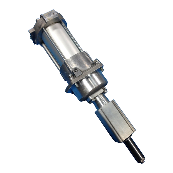
25B 16:1 Aluminum Pump
Customer Product Manual
Part 1044132-04
Issued 2/19
For parts and technical support, call the Industrial Coating
Systems Customer Support Center at (800) 433-9319 or
contact your local Nordson representative.
This document is subject to change without notice.
Check http://emanuals.nordson.com for the latest version.
NORDSON CORPORATION • AMHERST, OHIO • USA
Advertisement
Table of Contents

Related Manuals for Nordson 25B


Summary of Contents for Nordson 25B
- Page 1 For parts and technical support, call the Industrial Coating Systems Customer Support Center at (800) 433-9319 or contact your local Nordson representative. This document is subject to change without notice. Check http://emanuals.nordson.com for the latest version. NORDSON CORPORATION • AMHERST, OHIO • USA...
- Page 2 555 Jackson Street Amherst, OH 44001 Notice This is a Nordson Corporation publication which is protected by copyright. Original copyright date 2004. No part of this document may be photocopied, reproduced, or translated to another language without the prior written consent of Nordson Corporation. The information contained in this publication is subject to change without notice.
-
Page 3: Table Of Contents
Table of Contents Table of Contents Quick Reference − 25B 16:1 Aluminum Pump ....A 1-1 Introduction .......... - Page 4 ....B 5-7 25B Air Valve and Air Motor Repair ..... . .
- Page 5 Table of Contents 25B 16:1 and 27:1 Hydraulic Section Repair ....C 2-1 Introduction ..........
- Page 6 Table of Contents Part 1044132-04 E 2019 Nordson Corporation...
- Page 7 25B 16:1 Aluminum Pump Service Kits and Parts Refer to 25B Pump Manual 1044132 for complete service and parts information. For parts and technical support call (800) 433-9319. Air Motor Kits Air Valve Kits A - 106274 Seal Kit B - 106103 Seal Kit...
-
Page 8: Quick Reference − 25B 16:1 Aluminum Pump
A 1-1 Quick Reference − 25B 16:1 Aluminum Pump Section A 1 Quick Reference − 25B 16:1 Aluminum Pump Introduction Use this section for quick reference for the following information on the 25B 16:1 Aluminum pump: specifications service kits and packing glands... -
Page 9: Air And Fluid Specifications
I.D. Fluid inlet (siphon) size: in. NPT WARNING: Use Nordson or equivalent nylon or PTFE fluid hoses, with electrical continuity between fittings. Hoses must be capable of withstanding the maximum output pressure of the pump. Use flexible hoses between the pump and the fluid system to dampen vibration. -
Page 10: Part Number Quick Reference
Refer to the Pump Packing and Solvent Chamber Fluid Guide included with this manual for information on selecting the correct packing glands and solvent chamber fluids for your application. Contact your Nordson representative for additional information. Packing Glands for 16:1 Aluminum 25B Pumps... -
Page 11: Recommended Spare Parts
A 1-4 Quick Reference − 25B 16:1 Aluminum Pump Recommended Spare Parts Keep the following parts in inventory to avoid unplanned downtime. Quantities listed support a single pump. Adjust order quantities based on the number of pumps in service. Part... -
Page 12: Options
A 1-5 Quick Reference − 25B 16:1 Aluminum Pump Options Part Description Notes 1024722 ACCESSORY GROUP, air motor, Kit contains filter, regulator, lubricator, air hose, fittings, -inch brackets and fasteners, and lubricating oil. Refer to Section D1, Air Motor Parts for the kit parts list. - Page 13 A 1-6 Quick Reference − 25B 16:1 Aluminum Pump Part 1044132-04 E 2019 Nordson Corporation...
-
Page 14: Safety
Regulations and Approvals Make sure all equipment is rated and approved for the environment in which it is used. Any approvals obtained for Nordson equipment will be voided if instructions for installation, operation, and service are not followed. Part 1044132-04... -
Page 15: Personal Safety
The National Spray Equipment Manufacturers Association has created a wallet card that you should carry when you are operating high-pressure spray equipment. These cards are supplied with your equipment. The following is the text of this card: Part 1044132-04 E 2019 Nordson Corporation... -
Page 16: Fire Safety
Refer to local codes or your material MSDS for guidance. Do not disconnect live electrical circuits when working with flammable materials. Shut off power at a disconnect switch first to prevent sparking. Part 1044132-04 E 2019 Nordson Corporation... -
Page 17: Halogenated Hydrocarbon Solvent Hazards
Clean, maintain, test, and repair equipment according to the instructions in your equipment documentation. Use only replacement parts that are designed for use with original equipment. Contact your Nordson representative for parts information and advice. Halogenated Hydrocarbon Solvent Hazards Do not use halogenated hydrocarbon solvents in a pressurized system that contains aluminum components. -
Page 18: Safety Labels
Do not use halogenated hydrocarbon solvents in this system, it contains aluminum parts and may explode. Cleaning agents, coatings, paints or adhesives may contain halogenated hydrocarbon solvents. Don’t take chances, consult your material supplier to be sure. Part 1044132-04 E 2019 Nordson Corporation... - Page 19 B 1-6 Safety (Aluminum Pumps Only) Figure B 1-1 Safety Labels Figure B 1-2 ATEX Label Part 1044132-04 E 2019 Nordson Corporation...
-
Page 20: Description
Introduction This section provides you with a brief overview of 25B pump versions and applications, options, and pump operation. NOTE: The information in this section is common for all versions of the 25B pump. Pump Versions The 25B pump is available in the following versions:... -
Page 21: Packings
A small amount of leakage is normal. If the solvent cup fills quickly and overflows the packings need to be replaced. Both upper and lower packings should be replaced at the same time. Part 1044132-04 E 2019 Nordson Corporation... - Page 22 10. Pressure ball check 2. Air motor 7. Plunger 11. Siphon ball check 3. Hydraulic section 8. Solvent chamber 12. Siphon port 4. Shifting mechanism 9. Upper and lower packings 13. High-pressure port 5. Piston Part 1044132-04 E 2019 Nordson Corporation...
-
Page 23: Dead-End And Circulating System Operation
In-Line Check Valves, installed in the high pressure fluid line from the pump to prevent a reverse flow of fluid when the pump shifts direction, which could cause pump motoring. Part 1044132-04 E 2019 Nordson Corporation... -
Page 24: Installation
Follow the safety instructions in this document and all other related documentation. NOTE: The information in this section is common for all versions of the 25B Pump. All illustrations in this section show the 2:1 version of the pump, but installation procedures are same for all versions. -
Page 25: Grounding
See Figure B 3-1. Connect a ground wire or cable to the mounting bracket ground stud and to a true earth ground. The resistance to ground should not exceed 20 ohms. Part 1044132-04 E 2019 Nordson Corporation... -
Page 26: Siphon And High Pressure Fluid Connections
3. Return hose (customer-supplied) 5. Siphon hose −20 JIC x 1/4 in. NPT elbow −14 x in. NPT elbow 6. Drain hose and rod Note: Items 4 and 5 are included in the optional Wall Mounting kit. Part 1044132-04 E 2019 Nordson Corporation... -
Page 27: Compressed Air Connection
Install a self-relieving shutoff valve in the air supply line to the pump. Install the optional air filter/regulator/lubricator assembly so that the air supply enters the assembly at the filter and exits from the lubricator. Part 1044132-04 E 2019 Nordson Corporation... - Page 28 7. Lubricator 12. High-pressure fluid hoses 3. Drain valve 8. Air hose 13. Fluid filter 4. Air shut off valve (self-relieving) 9. Coating supply 14. Spray gun 5. Air filter 10. Siphon rod and strainer Part 1044132-04 E 2019 Nordson Corporation...
- Page 29 4. Air shut off valve (self-relieving) 11. Siphon hose 17. Drain valve 5. Air filter 12. High-pressure fluid hoses 18. Drain hose and rod 19. Waste container 6. Regulator and gauge 13. Fluid heater 7. Lubricator Part 1044132-04 E 2019 Nordson Corporation...
-
Page 30: Operation And Maintenance
NOTE: The information in this section is common for both the aluminum and stainless steel versions of the 25B Pump. All illustrations in this manual show the aluminum version of the pump. The stainless steel versions look different, but operate in the same way. -
Page 31: System Check
Solvent Chamber Fill Flushing Frequency Flush the pump or system before putting it into service for the first time before and after rebuilding the hydraulic section when changing coating material before a long term shutdown Part 1044132-04 E 2019 Nordson Corporation... -
Page 32: Cleaning Solution For Flushing
8. Place the siphon rod in the new coating material, then start the pump and run it until the new material has flushed out all of the cleaning solution and air. 9. Trigger the spray devices to flush out the cleaning solution and air. Part 1044132-04 E 2019 Nordson Corporation... - Page 33 7. Fluid filter 12. Drain rod 3. Air pressure regulator and gauge 8. Spray device 13. Waste container 4. Lubricator 9. Fluid heater 14. High-pressure fluid hose 5. Coating or cleaning solution supply 10. Circulation valve Part 1044132-04 E 2019 Nordson Corporation...
-
Page 34: Routine Startup
pump ratio = air pressure required WARNING: Maximum air pressure for all versions of the 25B pump is 7 bar (100 psi). Do not exceed this pressure. Calculate the required air pressure for desired output pressure as... -
Page 35: Routine Shutdown
If the system will be shut down for more than a few days, flush it and leave it filled with cleaning solution. 4. Perform daily maintenance as described in Maintenance in this section. Part 1044132-04 E 2019 Nordson Corporation... -
Page 36: Maintenance
Weekly See Figure B 4-3. Remove the rear safety cover. Lubricate the snapper pivot points (1) and the end of the ball stem (2) with molybdenum-disulfide grease. Part 1044132-04 E 2019 Nordson Corporation... -
Page 37: Every Four To Six Months
Flush the pump and system with a compatible cleaning solution. Change the solvent chamber fluid regularly. Remove the drain plug from the bottom of the solvent filler cup to drain the old fluid. Clean the exterior of the pump. Part 1044132-04 E 2019 Nordson Corporation... -
Page 38: Troubleshooting
These troubleshooting procedures cover only the most common problems that you may encounter. If you cannot solve the problem with the information given here, contact your local Nordson representative for help. Problem Page Pump fails to start or stops while operating and fails to... -
Page 39: Common Problems
Allow the pump to idle as it warms. If the leaking stops, refer to Preventing Air Valve and Muffler Freezing in this section. Continued... Part 1044132-04 E 2019 Nordson Corporation... - Page 40 Check for flow from the valve when it is closed. Output from spray devices Reduce the spray device nozzle or exceeds pump capacity fluid tip size. Reduce the number of spray devices connected to the pump. Reduce the circulation rate. Continued... Part 1044132-04 E 2019 Nordson Corporation...
- Page 41 Check the strainer screen. If the for coating material strainer screen is clogged with pigment, use a coarser mesh screen or a strainer without a screen. Contact your Nordson representative for advice. Pump continues to Coating material supply low, pump Fill the supply container.
- Page 42 Refer to problem 1. outer edges Material too viscous Add solvent or heat to the coating material to lower the viscosity. Damaged nozzle or fluid tip Replace the nozzle or fluid tip. Part 1044132-04 E 2019 Nordson Corporation...
-
Page 43: Minimizing Pressure Deviations
When the plunger contacts the fluid, a hydraulic shock and pressure spike is created. This hydraulic hammer also reduces packing, plunger, and siphon check valve life. Part 1044132-04 E 2019 Nordson Corporation... -
Page 44: Priming Problems
Install an air dryer to remove moisture from the air supply. Install larger mufflers. Remove the mufflers and install plumbing to exhaust the air to the outside of the building. Part 1044132-04 E 2019 Nordson Corporation... - Page 45 B 5-8 Troubleshooting Part 1044132-04 E 2019 Nordson Corporation...
-
Page 46: 25B Air Valve And Air Motor Repair
English hex wrench set flat-bladed screwdrivers molybdenum disulfide grease (Nordson part 900252) O-ring lubricant (Parker O-Lube or equivalent) (Nordson part 1612251) replacement parts or kits (refer to Section D1 Air Motor Parts) Part 1044132-04 E 2019 Nordson Corporation... -
Page 47: Air Valve Removal
C 1-2 25B Air Valve and Air Motor Repair Air Valve Removal 1. Shut off the air supply to the pump and relieve the air and fluid pressure. 2. Remove the mufflers and muffler adapters. 3. Disconnect the air supply hose and remove the air inlet nipple from the air motor. - Page 48 C 1-3 25B Air Valve and Air Motor Repair See Figure C 1-2. Finish removing parts from the air valve in the following order: 5. One screw (45) and poppet (50) from one side of poppet guide (49). 6. Screw (45) and end bushing (44).
-
Page 49: Snapper Rebuild
C 1-4 25B Air Valve and Air Motor Repair Snapper Rebuild See Figure C 1-3. Disassemble the snapper only to replace worn parts. CAUTION: The ball stem (32) and fork (31) are under spring tension. Remove the screw (55) carefully. -
Page 50: Air Valve Installation
C 1-5 25B Air Valve and Air Motor Repair See Figure C 1-2 on page C 1-3. Reassemble the air valve in the following order: 1. O-rings (48) in valve body bore. 2. Poppet guide (49), with one poppet (50) and screw (45) installed, in valve body (41). -
Page 51: Air Motor Repair
O-ring lubricant (Parker O-Lube or equivalent) (Nordson part 1612251) replacement parts or kits (refer to Section D1 Air Motor Parts) Preparation 1. If you are also going to repair the hydraulic section, flush the pump with a compatible cleaning solution. -
Page 52: Separating The Air Motor And Hydraulic Section
C 1-7 25B Air Valve and Air Motor Repair Separating the Air Motor and Hydraulic Section 1. See Figure C 1-4. Remove the four screws (27) and lock washers (28). 2. Pull the hydraulic section away from the air motor. - Page 53 C 1-8 25B Air Valve and Air Motor Repair Air Motor Disassembly (contd) Figure C 1-5 Air Motor Assembly 1. Screw 7. U-cup 16. Tie rods (3) 2. Lockwasher 8. Nuts (3) 20. Square O-rings (2) 3. Spool 9. Lock washers (3) 21.
-
Page 54: Piston Repair
C 1-9 25B Air Valve and Air Motor Repair Piston Repair Piston Disassembly CAUTION: Do not score the spool rod (5) or connecting rod (22). Any burrs will damage the seals and cause them to leak. 1. Put the piston assembly, connecting rod (22) up, in a vise with the upper jam nut (15) between the vise jaws. -
Page 55: Piston Assembly
C 1-10 25B Air Valve and Air Motor Repair Piston Assembly See Figure C 1-6. 1. Install the upper jam nut (15) onto the telescoping screw (17), with the recess for the special nut facing away from the slotted head of the telescoping screw. -
Page 56: Connecting The Air Motor And Hydraulic Section
C 1-11 25B Air Valve and Air Motor Repair 7. Air motor head on cylinder, making sure the: lip of the cylinder fits into the O-ring groove. connecting tube fits into the air port. spool rod fits through the center bore. - Page 57 C 1-12 25B Air Valve and Air Motor Repair Part 1044132-04 E 2019 Nordson Corporation...
-
Page 58: 25B 16:1 And 27:1 Hydraulic Section Repair
O-ring lubricant (Parker O-Lube or equivalent) (Nordson part 1612251) pipe thread adhesive/sealant (Nordson part 900481) threadlocking adhesive (Loctite High Temp 271) (Nordson part 900439) -
Page 59: Preparation
C 2-2 25B 16:1 and 27:1 Hydraulic Section Repair Preparation Dismounting the Pump 1. Flush the pump with a compatible cleaning solution. Refer to Flushing in Section B4, Operation and Maintenance. 2. Run the pump with very low air pressure. Remove the siphon rod from the cleaning solution and let the pump run dry. -
Page 60: Disassembly
C 2-3 25B 16:1 and 27:1 Hydraulic Section Repair Disassembly See Figure C 2-2. 1. Remove the hex head screws (15) and lock washers (14). Lift the solvent chamber (1) from the high pressure sleeve (8). 2. Unscrew the siphon check seat (13) from the siphon housing (10). - Page 61 C 2-4 25B 16:1 and 27:1 Hydraulic Section Repair Disassembly (contd) 5. See Figure C 2-3. Place the high pressure sleeve (8) upside down on two wood blocks so that the upper flange is resting on the blocks and the projecting portion of the upper packing gland (2) is between the blocks.
-
Page 62: Cleaning, Inspection, And Parts Replacement
C 2-5 25B 16:1 and 27:1 Hydraulic Section Repair Apply threadlocking adhesive part 900439 (Loctite High-Temp 271 or equivalent) to threads before installation. Figure C 2-4 Plunger Disassembly (Step 8) and Assembly 4. Plunger 6. Ball 5. Cage 7. Pressure check seat... -
Page 63: Packing Gland Replacement
C 2-6 25B 16:1 and 27:1 Hydraulic Section Repair Packing Gland Replacement NOTE: Always lubricate the packing gland exterior O-rings with O-ring lubricant before installation. Upper and lower packing glands can be ordered separately or together in a service kit. Except for Type G packings, the packing glands are shipped completely assembled. -
Page 64: Assembly
C 2-7 25B 16:1 and 27:1 Hydraulic Section Repair Assembly NOTE: Lubricate the packing gland external O-rings with O-ring lubricant before installing the glands. Tighten all threaded parts securely. See Figure C 2-4 on page C 2-5. 1. Install the pressure ball (6) on the pressure seat (7), then install the cage (5) on the seat. - Page 65 C 2-8 25B 16:1 and 27:1 Hydraulic Section Repair Assembly (contd) Figure C 2-6 Hydraulic Section Assembly Cutaway View 1. Solvent chamber 11. Cage 2. Upper packing gland 12. Ball 3. Plunger assembly 13. Siphon check seat 8. High pressure sleeve 14.
-
Page 66: Connecting The Air Motor And Hydraulic Section
C 2-9 25B 16:1 and 27:1 Hydraulic Section Repair Connecting the Air Motor and Hydraulic Section See Figure C 2-1 on page C 2-2. 1. Screw the connecting rod (C) into the plunger (3) and tighten securely. 2. Push the air motor and hydraulic section together. Install the four lock washers (B) and screws (A) and tighten them securely. - Page 67 C 2-10 25B 16:1 and 27:1 Hydraulic Section Repair Part 1044132-04 E 2019 Nordson Corporation...
-
Page 68: 25B Air Motor And Air Valve Parts
A dash (—) is used when the part number applies to all parts in the illustration. The number in the Part column is the Nordson Corporation part number. A series of dashes in this column (- - - - - -) means the part cannot be ordered separately. -
Page 69: Air Motor Parts
D 1-2 25B Air Motor and Air Valve Parts Air Motor Parts See Figure D 1-1. Item Part Description Quantity Note — 245546 MOTOR, air, 25B 323001 S VALVE, air, 4-way 981182 S SCREW, socket head, #12−28 x 1.75 in., steel... - Page 70 D 1-3 25B Air Motor and Air Valve Parts To Solvent Chamber (Section D2 Hydraulic Section Parts) Figure D 1-1 Air Motor Parts Part 1044132-04 E 2019 Nordson Corporation...
-
Page 71: Air Valve Parts
S WASHER, flat, 0.266 x 0.625 x 0.049 in., zinc NOTE A: Component of 25B air motor, part 245546. B: Noted parts are included in Service Kit, Seal, Air Valve, part 106103. Refer to page D 1-7 for kit parts list. - Page 72 D 1-5 25B Air Motor and Air Valve Parts Figure D 1-2 Air Valve Parts Part 1044132-04 E 2019 Nordson Corporation...
-
Page 73: Mufflers And Covers
D 1-6 25B Air Motor and Air Valve Parts Mufflers and Covers See Figure D 1-3. These parts are installed on the air motor. Item Part Description Quantity Note 245491 COVER, air motor, MDL 25B 245493 PANEL, back, MDL 25B... -
Page 74: Air Motor And Air Valve Service Kits
S WASHER, plate, end 940170 S O-RING, hot paint, 0.688 x 0.813 x 0.063 in. NOTE A: Used with new air valve center block. B: Not used on 25B pump; for 64B pump only. NS: Not Shown Part 1044132-04 E 2019 Nordson Corporation... -
Page 75: Air Valve Crankshaft And Arm Kit
D 1-8 25B Air Motor and Air Valve Parts Air Valve Crankshaft and Arm Kit See Figure D 1-2 on page D 1-5 for air valve parts. Item Part Description Quantity Note − 106314 SERVICE KIT, crankshaft and arm 246468... -
Page 76: Adhesives, Sealants, And Lubricants
D 1-9 25B Air Motor and Air Valve Parts Figure D 1-4 Air Motor Accessory Group Adhesives, Sealants, and Lubricants Use these adhesives, sealants, and lubricants when servicing your air motor. Refer to Section C1, Air Motor Repair for application instructions. - Page 77 D 1-10 25B Air Motor and Air Valve Parts Part 1044132-04 E 2019 Nordson Corporation...
-
Page 78: 25B 16:1 Aluminum Hydraulic Section Parts
A dash (—) is used when the part number applies to all parts in the illustration. The number in the Part column is the Nordson Corporation part number. A series of dashes in this column (- - - - - -) means the part cannot be ordered separately. -
Page 79: Type U Hydraulic Section Parts
See Figure D 2-1. Item Part Description Quantity Note − 245549 PUMP, hydraulic, 25B, 16:1, aluminum, Type U 245504 S CHAMBER, solvent 335380 S KIT, hydraulic service, 25B, 16:1, aluminum, Type U 940270 S S O-RING, hotpaint, 1.313 x 1.438 x 0.063... - Page 80 D 2-3 25B 16:1 Aluminum Hydraulic Section Parts Figure D 2-1 16:1 Aluminum Hydraulic Section Parts Part 1044132-04 E 2019 Nordson Corporation...
-
Page 81: Type F Hydraulic Section Parts
See Figure D 2-2. Item Part Description Quantity Note − 1077606 PUMP, hydraulic, 25B, 16:1, aluminum, Type F 245504 S CHAMBER, solvent 106292 S KIT, hydraulic service, 25B, 16:1, aluminum, Type F 940270 S S O-RING, hotpaint, 1.313 x 1.438 x 0.063... - Page 82 D 2-5 25B 16:1 Aluminum Hydraulic Section Parts Figure D 2-2 16:1 Aluminum Hydraulic Section Parts Part 1044132-04 E 2019 Nordson Corporation...
-
Page 83: Replacement Packing Glands
D 2-6 25B 16:1 Aluminum Hydraulic Section Parts Replacement Packing Glands Packing Glands and Hydraulic Service Kits for 16:1 Aluminum 25B Pump Packings Type A Type D Type F Type G Type U (std.) Upper — — — 503216 (A) —... -
Page 84: Siphon Ball And Seat Kit
D 2-7 25B 16:1 Aluminum Hydraulic Section Parts Siphon Ball and Seat Kit See Figure D 2-1 for parts locations. Item Part Description Quantity Note − 244826 SERVICE KIT, ball and seat 900001 S BALL, 440 stainless steel, 0.50 in., 50... -
Page 85: Type G Packing Gland Service Kit
Part Description Quantity Note − 106391 SERVICE KIT, Type G, packing, 25B, 16:1 940270 S O-RING, hot paint, 1.313 x 1.438 x 0.063 in. 983212 S WASHER, 0.882 x 1.275 x 0.035 in. - - - - - - S SPACER, U-cup 952171 S U-CUP, polyurethane, 0.812 x 1.312 in. -
Page 86: Options
Wall Mounting Kit See Figure D 2-4. Item Part Description Quantity Note − 245552 KIT, wall mount/siphon accessory, 25B, 16:1, 27:1, standard 972598 S ELBOW, male, 37, −14 x in. NPT, steel 824060 S HOSE, nylon, 5 ft 972100 S CONNECTOR, male, 37, −14 x... -
Page 87: Adhesives, Sealants, And Lubricants
D 2-10 25B 16:1 Aluminum Hydraulic Section Parts Adhesives, Sealants, and Lubricants Use these adhesives, sealants, and lubricants when repairing the hydraulic section. Refer to Section C2, Hydraulic Section Repair, for applications. Part Description Quantity 900439 ADHESIVE, threadlocking (Loctite High Temp 271) - Page 88 25B Air Motor Parts Nordson Customer Service: (800) 433-9319 245546 AIR MOTOR 981182 SOCKET-HEAD SCREW 983131 LOCK WASHER 323068 SPOOL 323061 941101 SQUARE O-RING O-RING (KIT A) 323067 SPOOL ROD 323073 SPOOL CARRIER GUIDE 323060 CYLINDER 984140 952450 983150 U-CUP...
- Page 89 25B Pump Air Valve Parts Nordson Customer Service: (800) 433-9319 323001 AIR VALVE 981107 SCREW 984130 983140 983120 LOCK WASHER LOCK WASHER 323017 SPACER 323016 BRACKET 323020 SNAPPER 983040 FLAT WASHER 981203 SCREW 323021 323013 FORK GASKET (KIT A) 323023...
- Page 90 25B 16:1 Aluminum Hydraulic Section Parts Nordson Customer Service: (800) 433-9319 SOLVENT CHAMBER 245504 UPPER PACKING GLAND (PACKING GLANDS AND KITS) O-RINGS 940270 PLUNGER 503396 CAGE 503134 (KIT A) BALL 900000 (KITS A, B) PLUNGER ASSEMBLY SEAT 503230 (KITS A, B)
- Page 91 ___________________ Date: 16Feb2017 Hallie Smith - Petee Engineering Manager Industrial Coating Systems Amherst, Ohio, USA Nordson Authorized Representative in the EU Person authorized to compile the relevant technical data. Contact: Operations Manager Industrial Coating Systems Nordson Deutschland GmbH Heinrich-Hertz-StraBe 42-44 D-40699 Erkrath Nordson Corporation ...
- Page 92 1. Fill the lubricator bowl with Nordson Vitalizer oil. NOTE: Use only Nordson Vitalizer oil or an oil recommended by your Nordson representative. Disregard any oil recommendations in the OEM instruction sheet shipped with the air lubricator.
- Page 93 Issued 1/04 Original copyright date 1991. Nordson and the Nordson logo are registered trademarks of Nordson Corporation. Part 108152−01 E 2017 Nordson Corporation...
- Page 94 Medium K, S Aliphatic Petroleum Naphthas High T, Q K, S Mild K, S Chlorinated Solvents Medium High K, S Note 1: Type U packings may swell slightly when exposed to aromatic hydrocarbon solvents. Part 108044G E 2003 Nordson Corporation...
- Page 95 Use for solventborne applications. esters NOTE: Type K solvent is highly viscous. At room temperature, it is not appropriate for use in Model 25B or 64B pumps where the solvent must flow through a filler cup and small ID passage into the solvent chamber.
- Page 96 4. Add the remaining distilled water to make one gallon, and mix for an additional 15 minutes. NOTE: The mixture may separate after prolonged shelf time. If it does, mix again before using. Part 108044G E 2003 Nordson Corporation...
- Page 97 Pump Packing and Solvent Chamber Fluid Guide Issued 10/03 Original copyright date 1990. Nordson and the Nordson logo are registered trademarks of Nordson Corporation. Part 108044G E 2003 Nordson Corporation...
Need help?
Do you have a question about the 25B and is the answer not in the manual?
Questions and answers