Table of Contents
Advertisement
Advertisement
Table of Contents

Related Manuals for Labounty CP 80


Summary of Contents for Labounty CP 80
- Page 1 Safety, Operation Maintenance Manual & Concrete Pulverizers Part Number T039705...
- Page 2 Continuing product development and improvement may have caused changes in the attachment that are not refl ected in this manual. If a question arises regarding the operation or maintenance of the attachment, contact a LaBounty dealer for the most current information available.
-
Page 3: Table Of Contents
TABLE OF CONTENTS Section 1 Introduction Introduction ..........................1-2 Understand Signal Words ......................1-2 Safety Summary .........................1-3 Label Locations ...........................1-4 Section 2 About the Attachment Model Description ........................2-2 Features ............................. 2-2 Concrete Pulverizer Terms ......................2-3 Concrete Pulverizer Glossary ..................... 2-4 Section 3 Installation Concrete Pulverizer Mounting Instructions ................3-2... - Page 5 CONCRETE PULVERIZERS SECTION 1 INTRODUCTION TO SAFETY Introduction ..........................1-2 Understand Signal Words ......................1-2 Safety Summary ........................... 1-3 Attachment Decals ........................1-4 Introduction to Safety Section 1 Page 1...
-
Page 6: Introduction
LaBounty, determine whether it is safe for you and others, and that the equipment will not be damaged or made unsafe as a result of your decision to implement it. -
Page 7: Safety Summary
Keep clear at a minimum of 15 feet (5 Ensure that the cab is equipped with the proper meters). safety guards for LaBounty applications. In addition, it is required that the cab be equipped with an approved Falling Object Protection Structure (FOPS) when processing materials. - Page 8 SAFETY SUMMARY continued DO NOT weld on any structural member unless specifi cally authorized by LaBounty. Any unauthorized NEVER remove any pins unless the attachment is on welding or welding procedures may result in personal the ground and blocked up or serious injury or death injury.
-
Page 9: Attachment Decals
CONCRETE PULVERIZERS ATTACHMENT DECALS STANLEY LABOUNTY BRAND DECALS (REPLACEMENT DECALS AVAILABLE UPON REQUEST) FIGURE 1-1 SAFETY FIRST DECAL PART NUMBER 503590 (INCLUDED WITH MANUALS) FIGURE 1-2 Introduction to Safety Section 1 Page 5... - Page 10 5,531,007 7,487,930 737,107 5,992,023 7,578,461 1,682,299 7,322,273 7,832,130 1,789,225 8,146,256 8,104,384 STANLEY LABOUNTY 1538 Highway 2 1-800-522-5059 Two Harbors, MN 55616 www.stanleyhydraulic.com FOREIGN PATENTS AND OTHER PATENTS PENDING 116404 PATENT PLATE PART NUMBER 116404 FIGURE 1-7 SAFETY DECAL PART NUMBER 503647...
-
Page 11: About The Attachment
CONCRETE PULVERIZERS SECTION 2 ABOUT THE ATTACHMENT Model Description ........................2-2 Features ............................2-2 Concrete Pulverizer Terms ......................2-3 Concrete Pulverizer Glossary ....................... 2-4 About the Attachment Section 2 Page 1... -
Page 12: Model Description
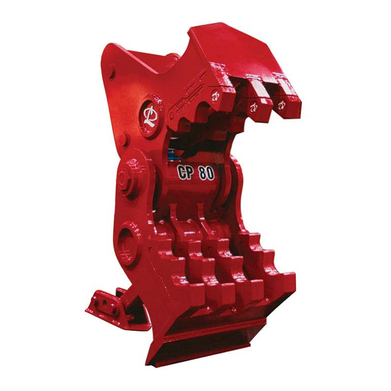
CONCRETE PULVERIZERS MODEL DESCRIPTION The LaBounty Concrete Pulverizer (CP) is a simple yet powerful tool that excels at separating rebar and con- crete, turning these two waste materials into recyclable, profi table products. It is a quiet alternative to tradi- tional demolition and concrete processing methods, such as hydraulic hammers and wrecking balls. - Page 13 CONCRETE PULVERIZERS ATTACHMENT TERMS UPPER JAW (MOVEABLE) MAIN PIVOT & MAIN PIN LOWER JAW (STATIONARY) EXCAVATOR STICK BUCKET CYLINDER POWER LINK LINK PIN SWIFT-LOCK TEETH AND TOOTH SEATS MOUNTING PAD GUIDE LINK POSITION ARM FIGURE 1-5 About the Attachment Section 2 Page 3...
- Page 14 CONCRETE PULVERIZERS ATTACHMENT GLOSSARY Build-up Welding process where worn off parent material is replaced with new metal. A very important maintenance procedure to extend the life of the pulverizer. Guide Link Part of the excavator bucket linkage that pins at one end to the excavator stick and pins at the other end to the bucket cylinder and the power link.
-
Page 15: Installation
CONCRETE PULVERIZERS SECTION 3 INSTALLATION Concrete Pulverizer Mounting Instructions .................. 2-2 Concrete Pulverizer Removal ....................... 2-5 Concrete Pulverizer Storage ......................2-5 Installation Section 3 Page 1... -
Page 16: Concrete Pulverizer Mounting Instructions
CONCRETE PULVERIZERS CONCRETE PULVERIZER MOUNTING INSTRUCTIONS It is recommended that the mounting bracket not be welded to the excavator stick until the pulverizer is installed. Mount the attachment as follows: 1. Postion the pulverizer on a fl at, level surface as shown in fi gure 3-1. Remove the main pin and link pin. 2. - Page 17 CONCRETE PULVERIZERS CONCRETE PULVERIZER MOUNTING INSTRUCTIONS continued SPOOL HEAD MAIN PIN (THREADED END) WASHER SLOTTED NUT COTTER PIN FIGURE 3-2 5. Extend the bucket cylinder and line up the power link with the linkage connection of the pulverizer. Install the link pin.
- Page 18 CONCRETE PULVERIZERS CONCRETE PULVERIZER MOUNTING INSTRUCTIONS continued 10. Weld the pad in position using E7018 low hydrogen welding rod. Make 1/2" (12.7 mm) fi llet welds, 3" (78 mm) long, 6" ((150 mm) on center (see fi gure 3-4). Run out welds 1-1/2" (40 mm) on ends and grind to taper in both the side view as shown in fi...
-
Page 19: Concrete Pulverizer Removal Instructions
CONCRETE PULVERIZERS CONCRETE PULVERIZER REMOVAL 1. Fully close the pulverizer and place it on a solid, level surface in the position shown in fi gure 3-7 . 2. Support the position arm while removing the pin from the mounting pad then lower the position arm to the ground. - Page 20 CONCRETE PULVERIZERS Page 6 Section 3 Installation...
-
Page 21: Operation
CONCRETE PULVERIZERS SECTION 4 OPERATION Before You Start ..........................4-2 What You’ll Need .......................... 4-2 First Things First ........................... 4-3 General Rules for Safe Operation ....................4-3 Attachment Controls ........................4-4 Getting the Feel of the Attachment ..................... 4-5 Feathering the Controls ........................ 4-5 Concrete Pulverizer Operating Tips .................... -
Page 22: Before You Start
BEFORE YOU START FIRST THINGS FIRST 1. Ensure all safe viewing distance decals are KNOW YOUR SAFETY PROGRAM installed and legible; contact LaBounty for 1. Read and understand the safety section of this replacements as required. manual and the base machine manual. -
Page 23: General Rules For Safe Operation
CONCRETE PULVERIZERS GENERAL RULES FOR SAFE 13. AVOID contacting machine with the attachment or any material held by it. OPERATION 14. Use machine swing for positioning only. DO NOT use the attachment as a jack hammer or wrecking 1. Read the Operator’s Manual for the excavator ball. -
Page 24: Attachment Controls
CONCRETE PULVERIZERS ATTACHMENT CONTROLS The LaBounty concrete pulverizer replaces the bucket of an excavator and operates with the same controls— no additional hydraulics are required. The bucket dump control opens the attachment and the bucket curl closes the attachment. Determine the control for each movement of the attachment before attempting to operate. Practice the machine movements as described in Getting the Feel of the Attachment section of this manual. -
Page 25: Getting The Feel Of The Attachment
CONCRETE PULVERIZERS GETTING THE FEEL OF THE Feathering the controls is a technique that will ATTACHMENT increase output and make operating the attachment easier. When starting any motion of the machine, Every operating part of any machine has a slightly move the control slightly from neutral until it starts different “operating feel”—an individual machine to move then smoothly move the control to increase... -
Page 26: Concrete Pulverizer Operating Tips
CONCRETE PULVERIZERS CONCRETE PULVERIZER OPERATING TIPS 1. To get the most crushing force from the pulverizer, pin the position arm in a mounting pad hole that allows the guide link to travel beyond 90º to the bucket cylinder before crushing begins (see fi gure 4-3). RANGE OF GREATEST PULVERIZING FORCE 90º... - Page 27 CONCRETE PULVERIZER OPERATING TIPS continued 3. The mounting pad of the LaBounty Concrete Pulverizer has three pin positions. By using the different positions, the angle of the lower (stationary) jaw can be adjusted (see fi gure 4-5). For each job, the lower jaw can be positioned to make the CP more productive or easier to use.
- Page 29 CONCRETE PULVERIZERS SECTION 5 MAINTENANCE Maintenance Safety Procedures ....................5-2 General Rules for Maintenance ......................5-3 Periodic Service Schedule ......................5-3 Daily Inspection Checklist ......................5-4 Concrete Pulverizer Lubrication ......................5-6 General Guidelines for Build-up and Hardsurfacing ................5-8 Build-up Recommendations ......................5-9 Hardsurfacing Recommendations ....................5 - 9 Tooth Build-up and Hardsurfacing ....................5-10 Attachment Build-up and Hardsurfacing ..................5-12 Bolt Torque Guidelines ........................5-14...
-
Page 30: Maintenance
OFF to prevent injury. arises regarding a safety or maintenance procedure, contact your LaBounty dealer. For the nearest LaBounty dealer, see the Contact Information at the front of this manual. • Inspect the attachment daily. DO NOT operate a... -
Page 31: Periodic Service Schedule
CONCRETE PULVERIZERS PERIODIC SERVICE DAILY SERVICE REQUIRED SCHEDULE Bolts: Check for looseness or damage. Retorque if necessary. Refer to Bolt Torque tables SERVICE THE ATTACHMENT AT in this manual. Bolts may be retorqued once, then SPECIFIED INTERVALS must be replaced. Connecting Pins and Pin Retaining Bolts: Inspect Inspect, lubricate, make service checks and for looseness, damage and/or wear on main pivot... -
Page 32: Daily Inspection Checklist
CONCRETE PULVERIZERS DAILY INSPECTION CHECKLIST Attachment Model _____________________Excavator Hour Meter________________________ Attachment Serial Number ______________________________ Date______________________ _______ 1. Visually inspect attachment for any damage. _______ a. Check for cracks or excessive wear that may cause structural failure _______ 2. Inspect the Swift-Lock teeth and tooth seats. _______ a. -
Page 33: Concrete Pulverizer Lubrication
CONCRETE PULVERIZERS CONCRETE PULIVERIZER LUBRICATION Grease all points every 4 hours of concrete pulverizer operation. Use Amoco Rykon premium grease No. 2EP or equivalent. Grease fi tting locations are indicated on the illustration (see fi gure 5-1, below) and by yellow GREASE decals on the attachment. - Page 34 CONCRETE PULVERIZERS SWIFT-LOCK TOOTH REPLACEMENT When the teeth are badly worn or crushing performance is decreased, the teeth should be replaced. Depending on the type of concrete being processed, the interval between teeth changes will vary. It is recommended that the teeth be replaced as a set for even wear and the best performance.
- Page 35 CONCRETE PULVERIZERS SWIFT-LOCK TOOTH REPLACEMENT continued 5. Insert the new tooth by sliding it into the slot in the seat. Make sure the retainer ring is located in its pocket in the tooth seat before installing the tooth (fi gure 5-3 on page 6). 6.
-
Page 36: General Guidelines For Build-Up And Hardsurfacing
WELD QUALITY Quality and attention to detail in welding can signifi cantly affect the life of the attachment. Stanley LaBounty strongly recommends that only qualifi ed and certifi ed welders perform this work. Make sure the weld con- sumables and base material are clean, dry, and free of grease, paint, dirt, or any other foreign substance that may harm the weld. -
Page 37: Build-Up Recommendations
NOTICE Do not use stainless hardsurface rod. It is too brittle for LaBounty applications and has a tendency to crack, weakening the base metal. Maintenance Section 5 Page 9... -
Page 38: Tooth Build-Up And Hardsurfacing
2. Place the build-up template along the tooth to de- termine the amount of build-up required (fi gure 4-5). BUILD-UP TEMPLATE Build-up templates can be ordered from LaBounty. 3. Preheat the tooth to about 200ºF (100ºC) to remove moisture. Preheat the area to be built up to 300-400ºF (150-200ºC). - Page 39 CONCRETE PULVERIZERS TOOTH BUILD-UP AND HARDSURFACING continued 5. Start hardsurfacing the tooth by applying parallel passes of AWS E7018 build-up running the length of the tooth (fi gure 5-6). These single passes should be 1/2" (13 mm) apart and will serve as an underlayment for the hardsurface rod.
-
Page 40: Attachment Build-Up And Hardsurfacing
Hazardous fumes can be generated when paint is jaws may be built up and hardsurfaced to increase heated. their life. Stanley LaBounty recommends that only • When sanding or grinding paint, do not breathe certain areas of the attachment be hardsurfaced. - Page 41 CONCRETE PULVERIZERS ATTACHMENT BUILD-UP AND HARDSURFACING (CONTINUED) 4. Apply a bead of Amalloy 814H rod or equivalent directly on top of each of the underlayment beads to create a 45º cross-hatch or “diamond” pattern on the approved sur- faces of the attachment. Space the beads approximately 1½...
-
Page 42: Metric Capscrew Size Guide
1. Always replace bolts and nuts with the same size and class of fastener. Replacement fasteners can be ordered from the LaBounty Parts Department to ensure the correct part is used. Unless otherwise speci- fi ed, use class 10.9 metric hex head capscrews, class 10.9 metric fl at head capscrews, and class 12.9 metric socket head capscrews. - Page 43 CONCRETE PULVERIZERS SWIFT-LOCK BUILD-UP TEMPLATE PARTS NUMBERS CP MODEL NUMBER PART NUMBER DESCRIPTION 307988 Template 307989 Outer Template 307990 Inner Template 304884 Template 304885 Build-up Template 304886 Build-up Template 307569 Template 307570 Template 307571 Template 304644 Build-up Template 304645 Build-up Template 304646 Build-up Template 173249...
- Page 44 1. All warranty claims require a claim number provided by Stanley LaBounty Service Department. 2. A factory-issued Return Material Authorization tag (RMA) must accompany returned product. 3. Returned product found defi cient by Stanley LaBounty will be replaced or repaired without charge FOB Distributor/Customer or will be credited to account balance.
- Page 46 T039705 (2012) The STANLEY and LABOUNTY names and logos are registered trademarks of Stanley Solutions...
Need help?
Do you have a question about the CP 80 and is the answer not in the manual?
Questions and answers