Table of Contents

Subscribe to Our Youtube Channel
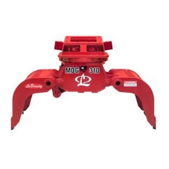
Related Manuals for Labounty MDG Series


Summary of Contents for Labounty MDG Series
- Page 1 MOBILE DEMOLITION GRAPPLE Safety, Operation & Maintenance 515933 User Manual 7/2018 Ver. 3 LaBounty | 1538 Hwy 2 | Two Harbors, MN 55616 | 1-800-522-5059 | www.stanleyinfrastructure.com/brands/labounty...
- Page 2 LaBounty dealer. You may also download a PDF copy at www.stanleyinfrastructure.com. REGISTRATION FORM The Warranty Registration Form must be filled out by the dealer or customer and returned to LaBounty indicating the date the machine went into service. POSSIBLE VARIATIONS LaBounty cannot anticipate every possible circumstance that might involve a potential hazard, as the owner’s...
-
Page 3: Table Of Contents
CONTENTS SAFETY .....................4 DECLARATION OF CONFORMITY ............6 DECALS & TERMS ..................7 INSTALLATION ..................8 Hydraulic Installation ................................8 Hydraulic Circuit Requirements ............................8 Removing MDG from the Excavator ..........................9 Storing MDG ...................................9 OPERATION ....................10 Before You Start ..................................10 Safety Devices ..................................10 Technical Specifications ..............................11 Controls ....................................11 Bleed the Hydraulic Circuit ..............................11 Operating Tips ..................................11... -
Page 4: Safety
Doing so will result in severe LaBounty, determine whether it is safe for you and others, personal injury or death from falling debris. and that the equipment will not be damaged or made unsafe as a result of your decision to implement it. - Page 5 • DO NOT weld on any structural member unless cancer or death. Protect yourself and those around specifically authorized by LaBounty. Any unauthorized you. Research and understand the materials you are welding or welding procedures will void the warranty, processing. Follow safety procedures and comply...
-
Page 6: Declaration Of Conformity
Representative in the Union: Patrick Vervier, Stanley Dubuis 17-19, rue Jules Berthonneau-BP 3406 41034 Blois Cedex, France. Vertreter in der Union/Représentant dans l’union/Representante en la Union/Rappresentante presso l’Unione Done at/Ort/Fait à/Dado en/Fatto a: Stanley Hydraulic Tools/LaBounty, 1538 Highway 2, Two Harbors, Minnesota, USA. 55616 Date/Datum/le/Fecha/Data:... -
Page 7: Decals & Terms
FIGuRE 3 RIGHT JAW SHELL LEFT JAW SHELL Grease Decal WEAR BLADE (At each fitting) P/N: 116388 FIGuRE 6 LaBounty Logo Decal FIGuRE 4 Safety First Decal (Included w/ manuals) P/N: 503590 FIGuRE 5 MDG Operating & Maintenance Manual | 7... -
Page 8: Installation
INSTALLATION Each MDG is shipped with a custom mounting bracket. Refer to the Parts Manual shipped with the attachment for specific installation information. 1. Locate flat, hard ground (e.g., concrete floor) for installation. Lift and place the attachment on the ground. Use blocking if necessary. -
Page 9: Removing Mdg From The Excavator
Do not check for hydraulic leaks with your hands. Hydraulic oil could inject into the skin. Seek immediate medical attention if an injection injury occurs 3. Visually check for hydraulic oil leaks or hydraulic hose interference. Note: Hydraulics will need to be bled before putting into service (see “Bleed the Hydraulic Circuit” on page 11). REMOVING MDG FROM THE EXCAVATOR 1. -
Page 10: Operation
• Ensure all decals are installed and legible. Contact avoid damage. LaBounty for replacements as required. • Maintain at least 50 feet (15 meters) between MDG • Have a DAILY safety dialog with all workers. Inform and any nearby power lines. -
Page 11: Technical Specifications
TECHNICAL SPECIFICATIONS Model Min. Excavator Weight MDG Weight Jaw Width Jaw Opening Jaw Capacity 11,000 Lbs 900 Lbs 28 in 59 in 0.3 yds³ MDG 70 5 mTons 400 Kg 710 mm 1,500 mm 0.2 m³ 22,000 Lbs 1,900 Lbs 31 in 71 in 0.5 yds³... -
Page 12: Maintenance
MAINTENANCE DAILY BEFORE USE INSPECTION CHECKLIST Inspect the attachment _______Inspect the hydraulic system for proper fluid level and fluid leaks (see “Hydraulic Inspection” on page 13). _______Inspect all bolts for damage (see “Inspect / Torque Bolts” on page 13). _______Inspect the Wear Blades and replace if necessary (see “Replace Wear Blades” on page 13). _______Lubricate (see “Lubrication”... -
Page 13: Hydraulic Inspection
HYDRAULIC INSPECTION Wear personal protection equipment at all times. This Trapped hydraulic pressure may be present after the includes eye protection, hard hat, steel toe shoes, base machine is shut off. Extreme caution must be leather gloves and hearing protection. taken when removing hydraulic hoses or injury or death could result. -
Page 14: Lubrication
LUBRICATION Wear Blade Hardware Wear Blade Conical FIGuRE 8 Nut Orientation FIGuRE 9 Use premium grease, No. 2EP. Grease fittings are indicated on the attachment by yellow “GREASE” decals. Grease each fitting with .3 oz (8 g) of grease. This is about 6 shots of grease from an average grease gun. Grease the attachment every 8 hours. -
Page 15: Rotation Head Lubrication
ROTATION HEAD LUBRICATION Rotation Head Lubrication FIGuRE 11 MDG Operating & Maintenance Manual | 15... -
Page 16: Parts Diagrams
PARTS DIAGRAMS GRAPPLE ASSEMBLY ‐ MDG 70 515035 MDG70 EXPLODED VIEW REV 1 16 | MDG Operating & Maintenance Manual... -
Page 17: Mdg70 Parts List
MDG70 PARTS LIST Item Description Part Number Main Frame Weldment 515594 Left Shell Weldment (Short Flange) 515595 Right Shell Weldment (Long Flange) 515596 Rotator Frame Weldment 515597 Linkage Weldment 515598 Cylinder Assembly (see page 18) 515599 Base 515600 Slewing Ring 515602 Main Hinge Pin - Ø... -
Page 18: Mdg140 Exploded View
V 1 MDG140 EXPLODED VIEW 18 | MDG Operating & Maintenance Manual... -
Page 19: Mdg140 Parts List
MDG140 PARTS LIST Item Description Part Number Item Description Part Number Main Frame Weldment 515414 Slewing Ring Seal 515364 Left Shell Weldment (Short Flange) 515421 Motor Assembly 515206 Right Shell Weldment (Long Flange) 515422 Rotator Frame Weldment 515423 Linkage Weldment 515424 Cylinder Assembly (see page 20) 515426... -
Page 20: Mdg160, 250, 310 & 400 Exploded View
GRAPPLE ASSEMBLY MDG160, 250, 310 & 400 EXPLODED VIEW 20 | MDG Operating & Maintenance Manual... -
Page 21: Mdg160, 250, 310 & 400 Parts List
MDG160, 250, 310 & 400 PARTS LIST Part Number Item Description MDG160 MDG250 MDG310 MDG400 Main Frame Weldment 515322 515246 515151 515517 Left Shell Weldment (Short Flange) 515323 515247 515152 515518 Right Shell Weldment (Long Flange) 515324 515248 515153 515519 Rotator Frame Weldment 515325 515249... - Page 22 Part Number Item Description MDG160 MDG250 MDG310 MDG400 Rotating Frame Hose Kit (6 pcs.) 515363 515298 515202 515564 Metal O-Ring Seal - Ø 106mm 515299 Metal Seal - Ø 106mm 515300 Slewing Ring Seal 515364 515301 515203 515203 Locker Set Linkage Axis Kit (Under/Short) 515366 515302 515204...
-
Page 23: Mdg70 & 140 Cylinder Parts List
MDG70 & 140 CYLINDER PARTS LIST MDG CYLINDER ASSEMBLY MDG70 MDG70 P/N MDG140 MDG140 Part Number Description 515599 P/N 515426 101 WTMG TUBE 515665 515494 Item 70 / 140 Description MDG70 MDG140 102 MCHG ROD 515666 515496 Cylinder Housing 515665 515494 103 MCHG HEAD 515667 515510 515666 515496 104 MCHG PSTN 515670... -
Page 24: Mdg160, 250, 310 & 400 Right Cylinder Parts List
MDG160, 250, 310 & 400 RIGHT CYLINDER PARTS LIST CYLINDER ASSEMBLY ‐ RH RH Cylinder MDG160 MDG250 MDG310 MDG400 Description P/N 515327 P/N 515251 P/N 515156 P/N 515522 102 MCHG ROD 515369 515308 515209 515574 Part Number 103 MCHG HEAD 515370 515309 515210 515575 Item Description MDG160 MDG250 MDG310 MDG400 104 MCHG PSTN 515374 515310... -
Page 25: Mdg160, 250, 310 & 400 Left Cylinder Parts List
MDG160, 250, 310 & 400 LEFT CYLINDER PARTS LIST CYLINDER ASSEMBLY ‐ LH LH Cylinder MDG160 MDG250 MDG310 MDG400 Part Number Description P/N 515328 P/N 515253 P/N 515157 P/N 515523 Item Description MDG160 MDG250 MDG310 MDG400 WTMG TUBE 515368 515306 515207 515570 Cylinder Housing 515368 515306 515207 515570 MCHG ROD 515369 515308 515209... -
Page 26: Mdg70 Swivel Parts List
MDG70 SWIVEL PARTS LIST SWIVEL ASSEMBLY ‐ MDG 70 515655 REV 1 Item Description Part Number # PART NUMBER DESCRIPTION Swivel Body 515676 515676 MCHG SWVL BODY Swivel Rotor 515677 515677 MCHG SWVL ROTR Swivel Cover 515678 515678 MCHG SWVL COVR Swivel Bolt Kit 515656 515656 KIT BOLT SWVL Relief Valve 515679 515679 VLV HYD RELIEF 515680 Hydraulic Adapter Kit KIT ADPT HYD... -
Page 27: Mdg140 ,160, 250, 310 & 400 Swivel Parts List
MDG140 ,160, 250, 310 & 400 SWIVEL PARTS LIST SWIVEL MANIFOLD ASSEMBLY Part Number Item Description MDG140 MDG160 MDG250 MDG310 MDG400 P/N 515360 P/N 515198 Swivel Body 515382 515382 515227 515227 515227 MDG P/N 515699 MDG Swivel Rotor 515383 515383 515228 515228 515228 Description 140/160 MDG 250 310/400 ... - Page 28 Additional copies of this manual are available by contacting your dealer or the LaBounty parts department, and requesting a CE Operation & Maintenance manual. You must include the attachment model number and serial number. LaBounty | 1538 Hwy 2 | Two Harbors, MN 55616 | 1-800-522-5059 | www.stanleyinfrastructure.com/brands/labounty...
Need help?
Do you have a question about the MDG Series and is the answer not in the manual?
Questions and answers