Leviton VerifEye 4100 Series Installation Manuals
Bi-directional compact modbus power and energy meter
Hide thumbs
Also See for VerifEye 4100 Series:
- Installation manual (30 pages) ,
- Installation manual (33 pages)
Table of Contents
Advertisement
Quick Links
Download this manual
See also:
Installation Manual
Installation Guide
Power Monitoring
RoHS
Compliant
DANGER
HAZARD OF ELECTRIC SHOCK, EXPLOSION, OR ARC FLASH
• Follow safe electrical work practices. See NFPA 70E in the USA, or applicable local codes.
• This equipment must only be installed and serviced by qualified electrical personnel.
• Read, understand and follow the instructions before installing this product.
• Turn off all power supplying equipment before working on or inside the equipment.
• Any covers that may be displaced during the installation must be reinstalled
before powering the unit.
• Use a properly rated voltage sensing device to confirm power is off.
DO NOT DEPEND ON THIS PRODUCT FOR VOLTAGE INDICATION
Failure to follow these instructions will result in death or serious injury.
A qualified person is one who has skills and knowledge related to the construction and
operation of this electrical equipment and the installation, and has received safety
training to recognize and avoid the hazards involved. NEC2009 Article 100
No responsibility is assumed by Levi t on for any consequences arising out of the use of this
material.
Control system design must consider the potential failure modes of control paths and, for
certain critical control functions, provide a means to achieve a safe state during and after a
path failure. Examples of critical control functions are emergency stop and over-travel stop.
WARNING
LOSS OF CONTROL
Assure that the system will reach a safe state during and after a control path failure.
Separate or redundant control paths must be provided for critical control functions.
Test the effect of transmission delays or failures of communication links.
Each implementation of equipment using communication links must be individually
and thoroughly tested for proper operation before placing it in service.
Failure to follow these instructions may cause injury, death or equipment damage.
1
For additional information about anticipated transmission delays or failures of the link, refer to
NEMA ICS 1.1 (latest edition). Safety Guidelines for the Application, Installation, and Maintenance
of Solid-State Control or its equivalent in your specific country, language, and/or location.
NOTICE
• This product is not intended for life or safety applications.
• Do not install this product in hazardous or classified locations.
• The installer is responsible for conformance to all applicable codes.
• Mount this product inside a suitable fire and electrical enclosure.
FCC PART 15 INFORMATION
NOTE: This equipment has been tested by the manufacturer and found to
comply with the limits for a class B digital device, pursuant to part 15 of
the FCC Rules. These limits are designed to provide reasonable protection
against harmful interference when the equipment is operated in a
residential environment. This equipment generates, uses, and can radiate
radio frequency energy and, if not installed and used in accordance with
the instruction manual, may cause harmful interference to radio
communications. This device complies with part 15 of the FCC Rules.
Operation is subject to the following two conditions:
(1) This device may not cause harmful interference, and
(2) this device must accept any interference received, including
interference that may cause undesired operation.
Modifications to this product without the express authorization of the
manufacturer nullify this statement.
For use in a Pollution Degree 2 or better environment only. A Pollution Degree 2
environment must control conductive pollution and the possibility of condensation or
high humidity. Consider the enclosure, the correct use of ventilation, thermal properties
of the equipment, and the relationship with the environment. Installation category:
CAT II or CAT III. Provide a disconnect device to disconnect the meter from the supply
source. Place this device in close proximity to the equipment and within easy reach of the
operator, and mark it as the disconnecting device. The disconnecting device shall meet
the relevant requirements of IEC 60947-1 and IEC 60947-3 and shall be suitable for the
application. In the US and Canada, disconnecting fuse holders can be used. Provide
overcurrent protection and disconnecting device for supply conductors with approved
current limiting devices suitable for protecting the wiring. If the equipment is used in a
manner not specified by the manufacturer, the protection provided by the device may
be impaired.
ModBus Power and Energy Meter
Product Overview
The E51 DIN Rail Power Meter provides a solution for measuring energy data with a single device. Inputs include
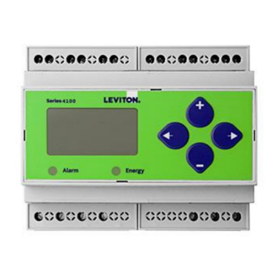
The VerifEye™ Series 4100 Bidirectional ModBus Meters feature bidirectional
Control Power, CTs, and 3-phase voltage. The E51 supports multiple output options, including solid state relay
monitoring specifically designed for renewable energy applications. The Series
contacts, Modbus (with or without data logging), and pulse. The LCD screen on the faceplate allows instant output
4100 meters are revenue-grade (ANSI C12.20 Class 0.2%) kWh electrical
viewing.
meters.
The E51 Meter is capable of bidirectional metering. Power is monitored in both directions (upstream and
The Series 4100 meters are available in standalone DIN rail mount or NEMA 4X
downstream from the meter). The meter is housed in a plastic enclosure suitable for installation on T35 DIN rail
enclosure. The 3-phase, advanced communication meters are compatible with
according to EN50022. The E51 can be mounted either on a DIN rail or in a panel. Observe correct CT orientation
when installing the device.
solid core, split core or flexible rope-style Rogowski current transformers.
Product Identification
Series 4DUMR
Series 41OUM
Specifications
1
Real Power and Energy
Reactive Power and Energy
Data Update Rate
Type of Measurement
Measured AC Voltage
Metering Over-Range
Frequency Range
Measurement Input Range
Series 4100
Bi-Directional Compact
Bi-Directional, ModBus Meter
Bi-Directional, ModBus in an Outdoor NEMA 4X
enclosure
MEASUREMENT ACCURACY
IEC 62053-22 Class 0.2S, ANSI C12.20 0.2%
IEC 62053-23 Class 2, 2%
Current 0.2% (+0.005% per °C deviation from 25°C) from 1% to 5% of range;
0.1% (+0.005% per °C deviation from 25°C) from 5% to 100% of range
Voltage 0.1% (+0.005% per °C deviation from 25°C) from 90 VAC
Sample Rate
2520 samples per second; no blind time
1 sec.
True RMS; one to three phase AC system
INPUT VOLTAGE CHARACTERISTICS
Minimum 90 V
(156 V ) for stated accuracy;
L-N
UL Maximums: 600 V (347 V ); CE Maximum: 300 V
+20%
Impedance
2.5 MΩ
/ 5 MΩ
L-N
L-L
45 to 65 Hz
INPUT CURRENT CHARACTERISTICS
CT Scaling
Primary: Adjustable from 5 A to 32,000 A
0 to 0.333 VAC or 0 to 1.0 VAC (+20% over-range), rated for use with
Class 1 voltage inputs
Impedance
10.6 kΩ (1/3 V mode) or 32.1 kΩ (1 V mode)
L-N
L-L
L-L
L-N
L-N
TM
to 600 VAC
L-L
Advertisement
Table of Contents

Related Manuals for Leviton VerifEye 4100 Series


Summary of Contents for Leviton VerifEye 4100 Series
- Page 1 Installation Guide Power Monitoring Series 4100 Bi-Directional Compact ModBus Power and Energy Meter Product Overview The E51 DIN Rail Power Meter provides a solution for measuring energy data with a single device. Inputs include The VerifEye™ Series 4100 Bidirectional ModBus Meters feature bidirectional Control Power, CTs, and 3-phase voltage.
- Page 2 Installation Guide Power Monitoring Series 4100 Modbus Specifications (cont.) CONTROL POWER AC 5 VA max.; 90V min.; UL Maximums: 600 V (347 V ); CE Maximum: 300 V DC* 3 W max.; UL and CE: 125 to 300 VDC Ride Through Time 100 msec at 120 VAC OUTPUT Alarm Contacts...
-
Page 3: Table Of Contents
Installation Guide Power Monitoring Series 4100 Modbus Table of Contents Dimensions Application Example Data Outputs Product Diagram Display Screen Diagram Installation Supported System Types Wiring Symbols Wiring Control Power Diagrams Quick Setup Instructions Solid State Pulse Output User Interface Menu Abbreviations Defined User Interface for Data Configuration Alert/Reset Information User Interface for Setup... -
Page 4: Dimensions
Installation Guide Power Monitoring Series 4100 Modbus Dimensions 1.8” (45mm) 1.9” (48mm) 2.3” (59mm) 1.5” (39mm) 3.6” 4.2” (91mm) (107mm) Bottom View (DIN Mount Option) Bottom View (Screw Mount Option) 2.4 “ 4.2 “ (61 mm) (107 mm) 1.2 “ 0.3 “... -
Page 5: Data Outputs
Installation Guide Power Monitoring Series 4100 Modbus Signed Power: Real, Reactive, and Apparent 3-phase total and per phase Data Outputs Real and Apparent Energy Accumulators: Import, Export, and Net; 3-phase total and per phase Reactive Energy Accumulators by Quadrant: 3-phase totals and per phase Configurable for CT &... -
Page 6: Installation
Installation Guide Power Monitoring Series 4100 Modbus Disconnect power prior to installation. Installation Reinstall any covers that are displaced during the installation before powering the unit. Mount the meter in an appropriate electrical enclosure near equipment to be monitored. Do not install on the load side of a Variable Frequency Drive (VFD), aka Variable Speed Drive (VSD) or Adjustable Frequency Drive (AFD). -
Page 7: Supported System Types
Installation Guide Power Monitoring Series 4100 Modbus The meter has a number of different possible system wiring configurations (see Wiring Diagrams section). To configure the meter, Supported System set the System Type via the User Interface or Modbus register 130 (if so equipped). The System Type tells the meter which of its Types current and voltage inputs are valid, which are to be ignored, and if neutral is connected. - Page 8 Installation Guide Power Monitoring Series 4100 Modbus Wiring WARNING RISK OF ELECTRIC SHOCK OR PERMANENT EQUIPMENT DAMAGE CT negative terminals are referenced to the meter’s neutral and may be at elevated voltages · Do not contact meter terminals while the unit is connected ·...
-
Page 9: Control Power Diagrams
• Select a voltage rating sufficient for the input voltage applied. • Provide overcurrent protection and disconnecting means to protect the wiring. For AC installations, use Leviton CTV00- FK3, or equivalent. For DC installations, provide external circuit protection. Suggested: 0.5 A, time delay fuses. -
Page 10: Quick Setup Instructions
Installation Guide Power Monitoring Series 4100 Modbus These instructions assume the meter is set to factory defaults. If it has been previously configured, check all optional values. Quick Setup – 1. Press the button repeatedly until SETUP screen appears. Instructions to the PASWD screen. -
Page 11: Solid State Pulse Output
Installation Guide Power Monitoring Series 4100 Modbus The meter has one normally open (N.O.) KZ Form Over-Current Protective Solid-State Device* (not supplied) A output and one normally closed (N.C.) KY Pulse Output solid-state output. One is dedicated to import ≤ 100 mA Power Source** energy (Wh), and the other to Alarm. - Page 12 IEEE Display Mode SETUP Demand M KVA M KVA DKVAR D KVA MKVAR MKVAR DEMND Maximum Reactive Maximum Apparent Maximum Real Present Present Maximum Real Maximum Reactive Maximum Apparent Present DEMND Power (S) Power (P) Reactive Power Power (P) Power (Q) Power (Q) Power (S) Real Power...
- Page 13 IEC Display Mode SETUP Demand DEMND Maximum Reactive Maximum Apparent Maximum Real Maximum Reactive Maximum Apparent Present Present Present Maximum Real DEMND Power Power Export Power (S) Real Power Reactive Power Apparent Power Power Import Power Power (Q) Import Demand Demand Demand Demand...
-
Page 14: Alert/Reset Information
Installation Guide Power Monitoring Series 4100 Modbus Alert/Reset To: ENRGY Information Alert Status PLOSS LOWPF F ERR I OVR V OVR PULSE (check if ALERT -------- -------- -------- -------- -------- -------- Wrench on A b C A b C A b C A b C Error LCD) - Page 15 Installation Guide Power Monitoring Series 4100 Modbus UI for Setup To Setup p. 2 “SPASS” RS-485 Output BAUD -------- Set Communications Parameters: ADDR - Modbus Address: 1 – 247. 38400 ADDR -------- 19200 + increments the selected (blinking) digit. Back S COM -------- nOnE...
- Page 16 Installation Guide Power Monitoring Series 4100 Modbus UI for Setup (cont.) To Setup p. 1 “S PWR” Set Phase Loss: VOLTS - Phase Loss Voltage: The fraction of the system voltage below which Phase Loss Alarm is on. For system types with neutral, the Line to Neutral voltage is also calculated and tested.
- Page 17 Daisy-chaining Devices to the Power Meter RS-485 The RS-485 slave port allows the power meter to be connected in a daisy chain format with up to 32 devices, assuming a Leviton Energ y Communications Monitoring HUB as the master device.
-
Page 18: Modbus Point Map Overview
Installation Guide Power Monitoring Series 4100 Modbus The Log Status Register has additional error flag bits that indicate whether logging has been reset or interrupted (power cycle, etc.) Modbus Point Map during the previous demand sub-interval, and whether the Real-Time Clock has been changed (re-initialized to default date/ time Overview due to a power-cycle or modified via Modbus commands). - Page 19 Installation Guide Power Monitoring Series 4100 Modbus Modbus Point Map R=read only R/W=read from either int or float formats, write only to integer format. Overview (cont.) Value is stored in non-volatile memory. The value will still be available if the meter experiences a power loss and reset. UInt Unsigned 16-bit integer.
- Page 20 Installation Guide Power Monitoring Series 4100 Modbus Modbus Point Map R/W NV Format Units Scale Range Description Integer Data: Summary of Active Phases • -2147483647 to SLong Real Energy: Net (Import - Export) +2147483647 • Accumulated • Real Energy: Quadrants 1 & 4 Real Energy ULong 0 to 0xFFFFFFFF...
- Page 21 Installation Guide Power Monitoring Series 4100 Modbus Modbus Point Map (cont.) R/W NV Format Units Scale Range Description Integer Data: Per Phase • Accumulated Real Energy, ULong 0 to 0xFFFFFFFF Phase A • • Accumulated Real Energy, ULong 0 to 0xFFFFFFFF Import Phase B •...
- Page 22 Installation Guide Power Monitoring Series 4100 Modbus Modbus Point Map (cont.) R/W NV Format Units Scale Range Description • Accumulated Apparent Energy, ULong kVAh 0 to 0xFFFFFFFF Phase A • • Accumulated Apparent Energy, ULong kVAh 0 to 0xFFFFFFFF Import Phase B •...
- Page 23 Installation Guide Power Monitoring Series 4100 Modbus Modbus Point Map (cont.) R/W NV Format Units Scale Range Description Configuration Reset: - Write 30078 (0x757E) to clear all Energy Accumulators to 0 (All). - Write 21211 (0x52DB) to begin new Demand Sub-Interval calculation cycle. Takes effect at the end of the next 1 second calculation cycle.
- Page 24 Installation Guide Power Monitoring Series 4100 Modbus Modbus Point Map (cont.) R/W NV Format Units Scale Range Description Phase Loss Voltage Threshold in percent of system voltage (register 134). Default value is 10 (%). Any phase (as configured in register 130) whose level drops below this threshold triggers a Phase Loss alert, i.e., if the System voltage is set to 480 V L-L, the L-N voltage •...
- Page 25 Installation Guide Power Monitoring Series 4100 Modbus Modbus Point Map (cont.) R/W NV Format Units Scale Range Description • UInt 0-32767 Count of Energy Accumulator resets • UInt Reserved (returns 0) Number of Sub-Intervals per Demand Interval. Sets the number of sub-intervals that •...
- Page 26 Installation Guide Power Monitoring Series 4100 Modbus Modbus Point Map (cont.) R/W NV Format Units Scale Range Description Floating Point Data: Summary of Active Phases • 257/258 R Float Accumulated Real Energy: Net (Import - Export) Real Energy: Quadrants 1 & 4 •...
- Page 27 Installation Guide Power Monitoring Series 4100 Modbus Modbus Point Map (cont.) R/W NV Format Units Scale Range Description • 287/288 R Float Volt Voltage, L-N (V), average of active phases • 289/290 R Float Current, average of active phases • 291/292 R Float 45.0-65.0...
- Page 28 Installation Guide Power Monitoring Series 4100 Modbus Modbus Point Map (cont.) R/W NV Format Units Scale Range Description • 365/366 R Float Real Power, Phase A • 367/368 R Float Real Power, Phase A Real Power (P) • 369/370 R Float Real Power, Phase A •...
-
Page 29: Sunspec Register Blocks
Installation Guide Power Monitoring Series 4100 Modbus This section describes the Modbus registers reserved for SunSpec compliance-related information. See www.sunspec.org for SunSpec Register Blocks the original specifications. R/W NV Format Units Scale Range SunSpec Name Description SunSpec 1.0 Common Model •... - Page 30 Installation Guide Power Monitoring Series 4100 Modbus SunSpec Register Blocks (cont.) R/W NV Format Units Scale Range SunSpec Name Description Power Real Power • 40088 SInt Watts M_AC_Power_SF -32767 to +32767 M_AC_Power Total Real Power (sum of active phases) • 40089 SInt Watts...
- Page 31 Installation Guide Power Monitoring Series 4100 Modbus SunSpec Register Blocks (cont.) R/W NV Format Units Scale Range SunSpec Name Description Apparent Energy • 40125 ULong M_Energy_VA_SF 0x0 to 0xFFFFFFFF M_Exported_VA Total Exported Apparent Energy • hours 40126 • 40127 ULong M_Energy_VA_SF 0x0 to 0xFFFFFFFF M_Exported_VA_A Phase A Exported Apparent Energy •...
- Page 32 Installation Guide Power Monitoring Series 4100 Modbus SunSpec Register Blocks (cont.) R/W NV Format Units Scale Range SunSpec Name Description • 40168 VAR- M_Export_VARh_ ULong M_Energy_VAR_SF 0x0 to 0xFFFFFFFF Phase A - Quadrant 4: Total Exported Reactive Energy • hours 40169 •...
-
Page 33: Troubleshooting
Installation Guide Power Monitoring Series 4100 Modbus Troubleshooting Problem Cause Solution The maintenance wrench There is a problem See the Alert sub-menu or the Diagnostic Alert Modbus Register 146 icon appears in the power with the inputs to the meter display. power meter.
Need help?
Do you have a question about the VerifEye 4100 Series and is the answer not in the manual?
Questions and answers