
Related Manuals for Leviton VerifEye 3300 Series


Summary of Contents for Leviton VerifEye 3300 Series
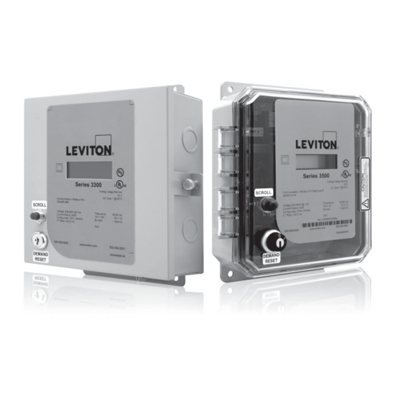
- Page 1 Series 3300 Multi-Function Meter with RS485 Communications Series 3500 Multi-Function Meter with Ethernet Communications Cat. No 3KUMT, 3NUMT, 3OUMT, 3RUMT Installation and User’s Manual PK-A3727-10-00-0A...
-
Page 3: Table Of Contents
TABLE OF CONTENTS 1 Product Description ....................1 1.1 General Description ...................1 1.2 Meter Features ....................1 2 Technical Specifications ..................2 2.1 Part Number Keys .....................2 2.2 Serial Number Description .................3 2.3 Electrical Specifications ..................3 2.4 I/O Connections and User Display ..............4 3 Installation Instructions ..................6 3.1 List of Materials ....................6 3.2 Mounting the Enclosure ..................6... - Page 4 Definitions Accuracy: The extent to which a given measurement agrees with the defined value. Demand: The average power or related quantity over a specified period of time. Demand-Maximum: The highest demand measured over a selected period of time. Percentage Error: The difference between percentage registration and 100%. Percentage Registration: The ratio of the actual registration to the true value, expressed as a percent.
- Page 5 Equipment used in a manner not specified by this document impairs the protection provided by the equipment. Failure to follow these warnings could result in serious injury or death. Bonding kit must be UL recognized. Leviton recommends Rockwell Automation 855BM-ABK...
- Page 6 • Do no use any cleaning agents, including water, on the VerifEye device. • No accessories are approved for use with the VerifEye meter other than those specified in the Leviton Manufacturing product literature and price sheets. • A circuit breaker used as a disconnect must meet the requirements of IEC 60947-1 and IEC 60947-3 (Clause 6.11.4.2)
- Page 7 • Current transformers may not be installed in an area where they block ventilation openings. • Current transformers may not be installed in an area of breaker arc venting. • Not suitable for Class 2 wiring method nor intended for connection to Class 2 equipment. •...
-
Page 8: Product Description
1 PRODUCT DESCRIPTION 1.1 General Description Series 3300/3500 Meters are revenue grade kWh electrical meters featuring Time of Use (TOU) meter readings, per-phase meter data, compatibility with either 3-phase 3-wire Delta or 3-phase 4-wire Wye configurations, and a user friendly LCD display. 1.2 Meter Features •... -
Page 9: Technical Specifications
2 TECHNICAL SPECIFICATIONS 2.1 Part Number Keys Series 3300/3500 Kits (CTs Included) 3 K U M R - 0 1 M Series Meter Type 3=3300/3500 M = Multifunction Kit Type Amperage Rating & CT Type K = Indoor Steel 01 = 100A Split Core O = Outdoor Plastic NEMA 4X 02 = 200A Split Core 04 = 400A Split Core... -
Page 10: Serial Number Description
2 TECHNICAL SPECIFICATIONS 2.2 Serial Number Description YYDDDA0000 Figure 1: Series 3300/3500 Serial Number Format 1. YY: Last two digits of the manufacturing year 2. DDD: Day of manufacture, 1-366 3. A: First digit of meter serial number, alphabetic A-Z 4. -
Page 11: I/O Connections And User Display
Occasionally, however, a temporary conductivity caused by condensation must be expected. Table 1: Series 3300/3500 electrical specifications Accuracy based on Leviton solid-core current transformers with 100 mA max output. Meter input burden resistance at 1.62 Ohms. 2.4 I/O Connections and User Display Pulse... - Page 12 2 TECHNICAL SPECIFICATIONS CT Inputs Current Transformer input, CT1. Colored wire of CT1 : X1 Current Transformer input, CT1. White wire of CT1 CT1 : X2 Current Transformer input, CT2. Colored wire of CT2 : X1 Current Transformer input, CT2. Colored wire of CT2 : X2 Current Transformer input, CT2.
-
Page 13: Installation Instructions
If technical assistance is required at any point during the installation, contact information can be found at the end of this manual. Leviton is not responsible for damage to the meter caused by incorrect wiring. -
Page 14: Making Conduit Holes
3 Installation Instructions 3.2.2 Making Conduit Holes Steel (Indoor) Enclosure The Series 3300/3500 steel enclosure comes with several 1 1/16” knockouts (3/4”conduit). Remove as needed to connect conduit fittings. Reference voltage and CT connections should enter in lower half of enclosure. Outdoor Plastic Enclosure The bottom, top, and non-hinge side of the plastic enclosure can be used as the conduit location in outdoor single meter enclosures. - Page 15 3 Installation Instructions 4.993 8.205 1.110 9.052 9.656 8.242 2.500 Figure 3: Series 3300/3500 Indoor Steel Enclosure Dimensions, in Inches...
-
Page 16: Installation Of Voltage Lines
3 Installation Instructions 0.82 8.54 11.06 9.54 10.12 6.00 Figure 4: Series 3300/3500 Outdoor (plastic) Enclosure Dimensions, in Inches Installation of Voltage Lines WARNING: Check to ensure service is disconnected before any connections are made. Verify if additional in line fuses are required based on National and Local electrical codes. 1. -
Page 17: Variations And Installation Of Current Transformers
General Requirements: • Splices on the CT leads must be within the meter enclosure, not inside the conduit. Leviton provided CT leads are 48 inches minimum. Wire insulation should be stripped so that the bare conductor length that connects to the meter terminal block does not exceed 0.300 inches. - Page 18 CT Variations • Leviton solid core CTs (Figure 6, left photo): In accordance with CT label, the LINE side of CT must face incoming Line. White lead connects to the appropriate X2 terminal. Black or colored lead connects to the appropriate X1 terminal.
- Page 19 3 Installation Instructions CT Installation Procedures 1. Route CT secondary wires through conduit if not already done. 2. Trim the wire to the appropriate length to avoid coils of excess wiring. 3. Strip wiring to approximately .300 inches. 4. Connect the CT leads to the appropriate terminals; see Hookup Diagrams in figures 8 and 9 below for correct CT orientations and connections.
-
Page 20: Securing The Enclosure
3 Installation Instructions Series 3300/3500 Meter 3PH 3W Hookup L2 L3 X1 X2 X1 X2 X1 X2 IMPORTANT! H1, white side, white dot, or labeled side of CTs must face source (LINE) black LOAD LINE blue Figure 9: 3-phase, 3-wire Delta (no-Neutral) hookup diagram Note: For Corner grounded systems leave neutral disconnected. - Page 21 3 Installation Instructions c. Power Factor Screens – Except in rare circumstances where predominantly inductive loads are metered, Power Factor values should have an absolute value greater than 0.6. A lower value indicates CTs installed on the wrong phase, backwards, or incorrectly connected at the meter, or voltage connections at the meter could be cross-phased.
-
Page 22: General Metering Features And Functionality
4 General Metering Features and Functionality Display Screen Number Main Numerical Display Parameter Indicators Phase Indicators Energy Flow Figure 10: Custom LCD sections Main Numerical Display and Scroll Button The main numerical display section indicates the numerical value of the current item. After startup sequence (see section 4.3) the display will revert to Real Energy (kWh) delivered (consumed). -
Page 23: Display Sequence And Screen Numbers
4 General Metering Features and Functionality Display Sequence and Screen Numbers See Appendix A for examples of each display. Table 4: Screen Numbers and Sequence Order Screen Numbers & Sequence Description of Displayed Value Real Time Clock Real Energy Delivered (kWh) Maximum Demand (MAX KW) Max Demand Time (MAX) Max Demand Date (MAX) -
Page 24: Descriptions Of Displayed Information
4 General Metering Features and Functionality The Meter Serial Number screen displays first. The lower left number is the alphabetical digit from the meter serial number (from 01=A to 26=Z), and the main display shows the numerical portion of the Serial Number. For example, a display showing “03” on the left and “6149” on the right below represents meter serial number XXXXXC6149, with the X‘s indicating the manufacturing day and year. - Page 25 4 General Metering Features and Functionality • Screen 01 – kWh – Real Energy Delivered (consumed), non-resettable. After initial startup the display reverts to and stays on this screen unless scroll or auto-scroll functions are initiated. The displayed value correlates to “kWh from grid” stored in Modbus or BACnet Address 0004 (see Sections 6 and 7).
-
Page 26: Manually Setting The Real Time Clock
4 General Metering Features and Functionality • Screens 14-17 – Real Power Delivered (consumed) kW A, kW B, kW C, kW SUM - Also known as Instantaneous Demand. Displayed values correspond to “Phase A Real Power,” “Phase B Real Power,” “Phase C Real Power,” and “Total Power (A+B+C)” in Modbus Register Map (see Appendix A). -
Page 27: Real Time Clock (Rtc) Battery Replacement
5 Real Time Clock (RTC) Battery Replacement If the battery depletes and no power is connected to the meter the RTC resets to 01/01/00 00:00:00 when power returns. The battery backup is a standard CR2025 lithium coin cell, rated at 3V and 165 mAh. -
Page 28: Communications - Series 3300 Rs485 Communication Models
6 Communications – Series 3300 RS485 Communication Models Modbus RTU Quick Start Guide Figure 12: RS485 Cable Entry Location Example of Communications Top Side Cable Entry Point WARNING: TO AVOID FIRE, SHOCK OR DEATH, turn off all power supplying equipment before working on or inside the equipment. - Page 29 6 Communications – Series 3300 RS485 Communication Models S3300 Meter S3300 Meter S3300 Meter S3300 Meter S3300 Meter Hub has built-in termination jumper Termination S3300 Meter S3300 Meter S3300 Meter jumper installed for this meter only. 4. Select Modbus address using the upper bank of DIP switches labeled “ADDRESS” as shown in Figure 14.
- Page 30 6 Communications – Series 3300 RS485 Communication Models 8. Before energizing the meter close and secure the enclosure door. Table 6. Modbus RTU Baud Rate Switch Settings Switch Baud Rate (Default) 9600 19200 38400 76800 Figure 14. Modbus RTU Switches...
-
Page 31: Bacnet Ms/Tp Quick Start Guide
6 Communications – Series 3300 RS485 Communication Models BACnet MS/TP Quick Start Guide WARNING: TO AVOID FIRE, SHOCK OR DEATH, turn off all power supplying equipment before working on or inside the equipment. Use a properly rated voltage sensing device to confirm power is off. - Page 32 6 Communications – Series 3300 RS485 Communication Models Figure 15. BACnet MS/TP Connections Non-Inverting (+) Inverting (-) Signal Common (C) Figure 16. BACnet MS/TP Switches Address Baud Rate...
-
Page 33: Communications - Series 3500 Ethernet Models
7 Communications – Series 3500 Ethernet Models BACnet IP and Modbus TCP Quick Start Guide WARNING: TO AVOID FIRE, SHOCK OR DEATH, turn off all power supplying equipment before working on or inside the equipment. Use a properly rated voltage sensing device to confirm power is off. -
Page 34: Communications - History Data Extraction
Modbus address 83 regardless of the meter’s normal Modbus address configuration. For diagnostic purposes, history data can be extracted from the meter using a Modbus RTU connection to the meter base unit. This feature is intended for trained field service personnel only. Contact Leviton Customer Support for assistance. -
Page 35: Data Extraction Procedure
8 Communications – History Data Extraction Data Extraction Procedure Historical readings or “data profiles” are not stored in standard Modbus registers. Instead, the historical readings are provided as a stream of data, controlled by a date filter and number of readings to be extracted. - Page 36 8 Communications – History Data Extraction Initiating Data Retrieval and Controlling the Number of Profiles Sent To initiate historical data retrieval, a read holding register command is issued to address 0506. The “number of registers” variable in the read command controls the number of historical profiles to be extracted. Once the desired number of readings has been found and transferred the transmission ends.
- Page 37 8 Communications – History Data Extraction Time of use Second Phase A Voltage Phase B Voltage Phase C Voltage Phase A Current Phase B Current Phase C Current Phase A Watts Phase B Watts Phase C Watts Total kWh + Total kWh - Total kVA + Total kVA -...
-
Page 38: Series 3300/3500 Pulse Outputs
Connecting Pulse Outputs to Data Acquisition Equipment. A variety of data acquisition equipment may be connected to the Series 3300/3500 pulse output terminals, including wireless pulse transceivers and data logging equipment. For information on Leviton‘s complete line of data acquisition products go to www.Leviton.com. -
Page 39: Diagnostic Tools And Frequently Asked Questions
10 Diagnostic Tools and Frequently Asked Questions 10.1 Diagnostic Tools Several diagnostic tools built into the Series 3300/3500 meter should be utilized to ensure the meter and CTs are installed correctly and functioning properly. 1. Energy Flow arrow (see Section 4.1, Figure 10) – Indicates direction of ‘energy flow‘ on amperage and kW screens. - Page 40 A: Industry convention for color coding in 3 Phase 208V electrical systems assigns the color black to phase A, red to phase B, Blue to phase C, and white to Neutral. Leviton‘s 100A and 200A solid core CTs are coded with the same colors (on the body of the CTs and on the wires) to help installers get each CT placed on the correct hot leg.
-
Page 41: Warranty And Contact Information
Leviton warrants to the original consumer purchaser and not for the benefit of anyone else that this product at the time of its sale by Leviton is free of defects in materials and workmanship under normal and proper use for five years from the purchase date. - Page 46 APPENDIX A Modbus Dip Switch Number Modbus Dip Switch Number Address Address...
- Page 47 Appendix A Modbus Dip Switch Number Modbus Dip Switch Number Address Address...
- Page 48 Appendix A Modbus Dip Switch Number Modbus Dip Switch Number Address Address...
Need help?
Do you have a question about the VerifEye 3300 Series and is the answer not in the manual?
Questions and answers