
Related Manuals for Leviton VerifEye 6000 Series


Summary of Contents for Leviton VerifEye 6000 Series
- Page 1 Series 6000 Multi-Function Panel Meter Cat. Nos. 60P00, 61P00, 62P00 Installation Manual PK-A3418-10-00-4A...
-
Page 3: Table Of Contents
TABLE OF CONTENTS Documentation ..........................1 Hazards and Warnings ........................2 Preliminary Operations .........................4 Introduction ............................5 Installation ............................14 Connection ...........................17 Communication ...........................21 Configuration ..........................22 Use ............................... 29 10 Alarms ............................30 11 Web Server ..........................33 12 Characteristics ..........................34 13 Performance Classes ......................... 39 14 Standard Statements and Warranty ................... -
Page 4: Documentation
1 DOCUMENTATION All documentation on the Series 6000 is available on the website at www.leviton.com. -
Page 5: Hazards And Warnings
The term “device” used in the paragraphs below refers to the Series 6000. The assembly, use, servicing and maintenance of this product must only be carried out by trained, qualified professionals. Leviton shall not be held responsible for failure to comply with the instructions in this manual. 2.1 Risk of electrocution, burns or explosion Caution: risk of electric shock. - Page 6 Any cable which needs to be replaced may only be replaced with a cable having the correct rating. • Despite constantly striving for quality in preparing this manual, errors or omissions are always a possibility and are not the responsibility of Leviton.
-
Page 7: Preliminary Operations
3 PRELIMINARY OPERATIONS To ensure the safety of staff and the equipment, it is vital to read and absorb the contents of these instructions thoroughly before commissioning. Check the following points as soon as you receive the package containing the device: •... -
Page 8: Introduction
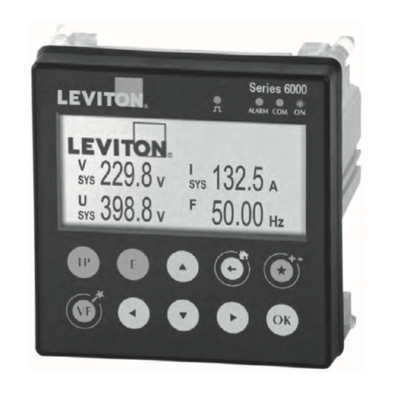
4 INTRODUCTION 4.1 Series 6000 Presentation The Series 6000 is a compact panel meter (PMD*) with a 96mm x 96mm format. It is designed for measuring, monitoring and reporting electrical energy. The Series 6000 offers a range of functions for measuring voltage, current, power, energy and quality. It allows the analysis of a single-phase or three-phase load. - Page 9 4 INTRODUCTION 4.1.2 Principle Current sensors (CTS and CRS models)
- Page 10 4 INTRODUCTION 4.1.3 Functions The Series 6000 boasts numerous functions, including: • General Measurements - Electrical values, voltage, current, frequency - Power, power factor, cos phi and tan phi - 4 quadrant operation - Predictive power - The overall accuracy of the Series 6000 + Sensors measurement chain guarantees up to class 0.5 (depending on the current sensor used) in power and active energy in accordance with IEC 61557-12 •...
- Page 11 4 INTRODUCTION Series 6000 Reference 60P00 61P00 62P00 Number of current inputs Metering Total and partial Ea+, Ea-, Er+, Er-, Eap • • • Multi-tariff (max. 8) • • • Multi-measurement V1, V2, V3, Vn, U12, U23, U31, f I1, I2, I3, IN •...
- Page 12 4 INTRODUCTION 4.1.4 Dimensions 3.58 in. 2.67 in. 0.62 in. 91 mm. 67.8 mm. 15.8 mm. 3.88 in. 98.5 mm. 4.1.5 Front panel 1. Screen 350 x 160 2. LEDs 3. 10 capacitive touch keys...
- Page 13 4 INTRODUCTION The display consists of a screen and 10 keys: Shortcut keys for load measurements: current, active power, reactive power, apparent power, power factor, cos phi Shortcut keys for electrical network measurements: phase-to-neutral voltage, phase-to-phase voltage, frequency Shortcut keys for the Wizard by holding down Shortcut keys for active, reactive, apparent energy meters (total and partial values) Arrow keys for navigation...
- Page 14 Current sensors (CTS and CRS models) For connecting the current sensors, use Leviton branded cables only, CCSRJ straight cables, twisted pair, unshielded, 600 V, -10°C / +70°C. It is recommended that all the current sensors are installed in the same direction.
- Page 15 4 INTRODUCTION 4.2.2 CTS split-core current sensors The CTS series split-core current sensors are used to set up measurement points in a new or existing installation without interfering with its cabling. Thanks to the specific link, they are recognized by the Series 6000 and the overall accuracy of the measurement chain is guaranteed.
- Page 16 4 INTRODUCTION 4.2.3 CRS flexible current sensors The CRS flexible current sensors use the Rogowski principle, covering a wide current range without saturation. Their flexible design and easy opening system enables a quick installation inside electrical panels, making them particularly well suited for adding measuring points in existing electrical installations, especially when space is limited.
-
Page 17: Installation
5 INSTALLATION The following paragraphs describe the installation of the Series 6000 and associated sensors. 5.1 Recommendations and safety Refer to the safety instructions (section “2. Hazards and warnings”, page 4) • Keep away from electromagnetic interference generator systems. • Avoid vibrations with accelerations greater than 1 g for frequencies lower than 60 Hz. •... - Page 18 5 INSTALLATION 5.4 Installing CTS split-core sensors 5.4.1 Cable mounting Install on 300V insulated cables only! Sharp edges Recommended installation Do NOT clamp or pull out NON-INSULATED conductors carrying DANGEROUS VOLTAGE which could cause an electric shock, burn or arc flash. Ref.
- Page 19 5 INSTALLATION 5.5 Installing CRS Flexible current sensors 5.5.1 Bar or cable mounting Centered position for the best measurement Do NOT clamp or pull out NON- INSULATED conductors carrying Centered position for the best measurement DANGEROUS VOLTAGE which could cause an electric shock, burn or arc flash.
-
Page 20: Connection
6 CONNECTION 6.1 Series 6000 connection Series 6000 (60P00, 61P00, 62P00) 2x OUTPUT x= 7 mm 0.25 N.m 30 VDC - 20 mA max. - SELV 0.14 mm² - 1.5 mm² max. 3x INPUT x= 7 mm 0.25 N.m 12 VDC - 27 mA max. - SELV 0.14 mm²... - Page 21 6 CONNECTION Description of the terminals Sensors Supply CTS/CRS sensors 110-277VAC L/N 50-60Hz 277-400VAC L/L' 50-60Hz 120-300 VDC I 01 I 02 I 03 0.5 A gG / BS 88 2A gG / 0.5 A class CC Listed fuses for UL application L / + N / - 3x Inputs...
- Page 22 6 CONNECTION 6.2 Connection to the electrical network and to the loads The Series 6000 can be used on single-phase, two-phase or three-phase circuits. 6.2.1 Configurable loads based on the network type The table below summarizes the load that it is possible to configure depending on the type of network at the installation.
- Page 23 6 CONNECTION Three-phase + Neutral Three-phase Three-phase 3P+N – 3CT 3P – 3CT 3P – 2CT (1 three-phase load + measured Neutral) (1 three-phase load) (1 unbalanced three-phase load) V1 V2 V3 VN V1 V2 V3 VN V1 V2 V3 VN Two-phase + Neutral Three-phase Three-phase...
-
Page 24: Communication
A 120 Ohm resistor must be fixed at both ends of the connection. 7.3 Modbus and Profibus communication tables The Modbus and Profibus communication tables and the associated explanations are available on the Series 6000 documentation page on the website at www.leviton.com. -
Page 25: Configuration
The device can be configured directly from the Series 6000 screen or with the Easy Config software. The following paragraphs describe configuration with Easy Config for different types of communication architecture and several types of connected Leviton products. 8.1 Configuration using Easy Config 8.1.1 Connection modes... - Page 26 8 CONFIGURATION 8.1.2 Using Easy Config Easy Config is configuration software used to set product parameters easily and quickly. Parameters are set in successive steps: For each setting selected a customized screen appears, depending on the connected product.
- Page 27 8 CONFIGURATION Load configuration The type of load can be accessed in the load configuration menu. The user can also define its nominal current, the name of the load, its usage and its location within the electrical installation. The user selects the nominal voltage, the network frequency, the direction of phase rotation and whether or not a voltage transformer is used.
- Page 28 8 CONFIGURATION Alarms The type of alarm and the configuration are set in Easy Config, see section “10. ALARMS”, for further details. Other settings The other settings, such as Memory allocation, Multi-tariff, Inputs/Outputs, Quality events, Communication and other controls are also carried out with Easy Config. Example of the screen for setting the Quality parameters of the electrical network:...
- Page 29 8 CONFIGURATION 8.2 Configuration from the display 8.2.1 Navigation To access navigation, press “OK” to view the different menus available: 8.2.2 Description of the Wizard The wizard allows very fast configuration of the main parameters of the Series 6000: The wizard is launched automatically at the first use and on demand for later uses. It is also possible to access the wizard by holding down the “VF”...
- Page 30 8 CONFIGURATION 8.2.3 Complete configuration To access the complete configuration of the product and in particular the configuration of the alarms and of the additional parameters not covered by the Wizard, select the “PARAMETERS” menu: Enter the password “100” using the arrow pad (4 arrow keys) and confirm with “OK”: This gives access to the whole configuration of the Series 6000: •...
- Page 31 8 CONFIGURATION 8.3 Screen menu structure Menu structure Phase-neutral voltage Phase-phase voltage Frequency Phase-neutral voltage unbalance THD Phase-neutral voltage THD Phase-neutral network Voltages Phase-neutral voltage harmonics Phase-neutral voltage crest factor Phase-phase voltage unbalance THD Phase-phase voltage Phase-phase voltage harmonics Phase-phase voltage crest factor Current System Current Current Unbalance...
-
Page 32: Use
9 USE 9.1 Browse Browsing through the “MEASUREMENTS” menu allows access to all the measurements. 9.2 Shortcuts The shortcut keys of the display “IP”, “E”, “VF” allow quick access to the current, power, energy, voltage or frequency measurements. Shortcut keys for load measurements: current, active power, reactive power, apparent power, power factor, cos phi Shortcut keys for electrical network measurements: phase-to-neutral voltage, phase-to-phase voltage, frequency... -
Page 33: Alarms
10 ALARMS 10.1 Alarms upon events Alarms can be generated when a threshold is exceeded for the electrical measurements, consumption, variations in level or change in input status. Also, combinations can be made on the alarms created. Up to 50 alarms detected are saved and timestamped; an alarm can have 3 distinct statuses: Alarm active, Alarm completed, Alarm completed and acknowledged. - Page 34 10 ALARMS 10.1.3 EN 50160 voltage quality events • Alarms on quality events for the voltage provided: voltage dips (Udip), temporary overvoltages (Uswl) and voltage outages (Uint). 10.1.4 Consumption • Alarm on the energies: Ea+, Ea-, Er+, Er-, Eap • Selection of a high threshold (excessive consumption) 10.1.5 Digital inputs •...
- Page 35 10 ALARMS 10.2 System alarms If an installation error is detected during setup, an alarm will be automatically generated. 10.2.1 Current/voltage compatibility • Alarm upon connection error between the current and the voltage • Requires a certain load level: 0.6 < PF < 1 and I > 2% In 10.2.2 Incorrect direction of rotation (three-phase network) •...
-
Page 36: Web Server
11 WEB SERVER The Ethernet version of the Series 6000 (61P00), has an embedded web server. This web server allows access to all the measurements of the electrical parameters and of the energy measured by the meter. The default IP address for accessing the web server is the following: 192.168.0.4 Below are some examples of the web server screen:... -
Page 37: Characteristics
12 CHARACTERISTICS 12.1 Series 6000 characteristics 12.1.1 Mechanical features Casing type Fitted on a door with format 96x96 Protection degree IP52 front panel / IP20 rear panel Capacitive touch-screen technology, 10 keys Screen resolution: Type of screen 350 x 160 pixels ref 60P00: 326 g Weight ref 61P00: 341 g... - Page 38 Split-core CTS, flexible CTR current sensors Class 0.2 Series 6000 only Accuracy Class 0.5 with CTS or CTR sensors Connection Specific Leviton cable with RJ12 connectors 12.1.4 Input/output characteristics Inputs Accuracy Optocoupler with internal (12 VDC ± 10%) or external (12-24 VDC± 20%)
- Page 39 12 CHARACTERISTICS PROFIBUS Product 62P00 Link RS485 - SELV Protocol PROFIBUS DPV1 Functions PROFIBUS communication Connection SubD9 Connector Connection USB 2 Protocol Modbus RTU on USB Function Configuration Connection Type B micro USB connector 12.1.6 Environmental specifications IP52 front IP20 rear Ambient operating temperature -10 - +70°C (IEC 60068-2-1 / IEC 60068-2-2) Storage temperature...
- Page 40 12 CHARACTERISTICS Immunity to conducted disturbances, induced by IEC 61000-4,-6 Power supply LEVEL III Criterion A radio-frequency fields Voltage measurement Criterion A LEVEL III Criterion A Current inputs LEVEL III Criterion A RS485 LEVEL III Criterion A Ethernet LEVEL II Criterion A Profibus LEVEL III Criterion A...
- Page 41 Storage temperature -25 - +85°C Relative humidity 95% RH without condensation Altitude < 2,000 m UL 61010 Leviton RJ12 cable, straight, twisted pair, unshielded, 600 V Connection -10 / +70 °C - SELV CRS - Flexible current sensor Model CRS4K CRS6K...
-
Page 42: Performance Classes
Total harmonic distortion rate of the THDi, THD-Ri current (relative to the fundamental, 1 with CTS or CRS sensors Orders 1 to 63 relative to the efficient value) Current harmonics 1 with CTS or CRS sensors Centralized remote control signals *With Leviton connection cables. - Page 43 13 PERFORMANCE CLASSES 13.1 Specification of the characteristics Overall operating performance class Series 6000 + Measurement Symbol Function dedicated sensors (CTS & CRS) in range compliance with IEC 61557-12 Frequency 0.02 45 - 65 Hz 5% - 120% In 0.2 Series 6000 only Phase current 10% - 120% In 0.5 with CTS &...
-
Page 44: Standard Statements And Warranty
LIMITED 5 YEAR WARRANTY AND EXCLUSIONS Leviton warrants to the original consumer purchaser and not for the benefit of anyone else that this product at the time of its sale by Leviton is free of defects in materials and workmanship under normal and proper use for 5 years from the purchase date.
Need help?
Do you have a question about the VerifEye 6000 Series and is the answer not in the manual?
Questions and answers