Table of Contents
Advertisement
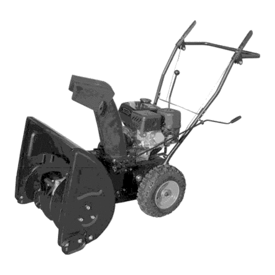
5.5 HP 2 Stage
Snow Thrower
SKU #270-3250
Owner's
Manual
DO NOT
RETURN
TO STORE
Questions?
Problems?
Please
call our customer
help
line:
(888) 315-3080
M-F 84 CT
IMPORTANT:
PLEASE
READ
THIS ENTIRE
MANUAL
BEFORE
USING
THIS SNOW
THROWER.
Thank you for purchasing
a Yardworks ®snow thrower. This manual provides information
regarding
the setup, operation,
and maintenance
of this product. We have made every effort to
ensure the accuracy of the information
in this manual. The manufacturer
reserves the right to
change this product at any time without prior notice.
Please keep this manual available to all users during the entire life of the snow thrower.
Copyright
2005 Yardworks(R).
Do not reprint
without
written
authorization.
Advertisement
Table of Contents

Related Manuals for Yardworks 270-3250


Summary of Contents for Yardworks 270-3250
- Page 1 Please keep this manual available to all users during the entire life of the snow thrower. Snow Thrower SKU #270-3250 Owner's Manual READ THIS ENTIRE...
-
Page 2: Table Of Contents
TABLE OF CONTENTS GENERAL SAFETY PROCEDURES ... PACKAGE CONTENTS ... SNOW THROWER COMPONENTS ... ENGINE COMPONENTS ... ASSEMBLY ... Chute Assembly ... Handle Assembly ... Attaching Drive Speed Control Lever ... Chute Rotation Handle ... Drive Control and Auger Control Cable Assembly ... PREPARING THE SNOW THROWER FOR USE ... -
Page 3: General Safety Procedures
GENERAL SAFETY PROCEDURES Please familiarizeyourselfwith the following safetysymbolsandwords: The safety alert symbol A is used with one of the safety words (DANGER, or WARNING) to alert you to hazards. Please pay attention to these hazard notices both in this manual and on the snow thrower. DANGER: Indicates a hazard that will result in serious injury or death if instructions... - Page 4 A WARNING: Foreign objects jams, projectiles, and other dangerous • Do not use in the path of wires, doormats, • If the snow thrower intakes a foreign object, stop the engine, wait for the auger and impeller to stop rotating, and inspect the snow thrower for damage. •...
- Page 5 A WARNING: In addition precautions that should be followed • Read all manuals and warning labels before using a machine. • Never operate a machine with any guard or cover removed. • Remove all adjusting keys and wrenches • Do not allow children or uninstructed •...
-
Page 6: Package Contents
PACKAGE CONTENTS Your snow thrower comes with the items listed below. following items are included with your snow thrower. If you are missing components (888) 315-3080 8-5 CT for customer ITEM LIST Please check to see that all of the DO NOT RETURN TO STORE,... -
Page 7: Snow Thrower Components
SNOW THROWER Please familiarize yourself with the locations and functions of the various components and controls of the snow thrower. (1) Drive Control- Drives the snow thrower pre-selected speed and direction when depressed. (2) Handle- Hold the snow thrower here when using. (3) Auger Control- Rotates the auger when... -
Page 8: Engine Components
ENGINE COMPONENTS Please familiarize yourself with the locations and functions of the various components and controls of the engine portion of the snow thrower. (1) Recoil Starter Handle- Pull-cord for starting engine. (2) Throttle Lever- Use to control engine speed. This should be set to the highest speed when using the snow thrower. -
Page 9: Assembly
ASSEMBLY In order to best protect the snow thrower while in the package, this product comes with some components disassembled. proceeding to use the snow thrower. For ease of assembly, we recommend components in the order listed in this manual. If after reading this section,... -
Page 10: Attaching Drive Speed Control Lever
NOTE: For easiest a ssembly, w e recommend not attachingthelower bolt of eachhandle bracketuntil after assembling the chuterotationhandle,augeranddrive handlecables, anddrive speed controllever. Figure 2- Handle Assembly Attaching Drive Speed Control Lever To attach the drive speed control lever, slide it through the drive speed selection hole in the handle and attach it at the base of the snow thrower using two bolts and two nuts as shown in figure 3. -
Page 11: Chute Rotation Handle
Chute Rotation Handle To attach the chute rotation handle: 1. Remove the handle grip from the handle by removing figure 4). Slide the end of the chute rotation handle, with the grip removed, hole on the snow thrower handle as shown in figure 4 a. Slide the other end of the chute rotation handle through the hole near the base of the chute. - Page 12 NOTE: When attaching the cables, be sure they are properly threaded through the main handle. The auger control cable should fit through the hole next to the speed selector. The drive control cable should fit in the handle groove on the other side of the speed selector.
-
Page 13: Preparing The Snow Thrower For Use
PREPARING THE SNOW THROWER The following section describes steps you must follow to prepare for use. If after reading this section, you are unsure about how to perform steps please call (888) 315-3080 perform these steps properly can damage the snow thrower or shorten Visually Inspect the Snow... -
Page 14: Add/Check Gasoline
Remove the oil filler cap again and inspect the attached dipstick. be visible on the stick. oil and repeat steps 4 and 5. Replace the oil filler cap and screw tightly. NOTE: Even if you have previously common when adding oil to the crankcase. sufficient oil by checking the dipstick. -
Page 15: Adjust Skid Shoes
IMPORTANT: • Never use an oil/gasoline mixture. • Never use old gas. • Avoid getting dirt or water in the fuel tank. • Gas can age in the tank and make it hard to start up the snow thrower in the future. -
Page 16: Operation
OPERATION Before starting the snow thrower, make sure you have read and performed steps in the "Preparing the Snow Thrower for Use" section of this manual. unsure about how to perform 3080 8-5 CT for customer Starting the Snow Thrower To start up the snow thrower, perform the following steps: 1. -
Page 17: Using The Snow Thrower
Pull on the recoil starter handle slowly until a slight resistance 10) then pull quickly to start the engine. Return cord gently into the machine. Never allow the cord to snap back. If engine fails to start, repeat step 5. NOTE: After repeated engine, please consult the troubleshooting problems persist please call (888) 315-3080 Once the engine has started and run for about a minute, move the choke lever... - Page 18 You can adjust the drive speed and direction using the drive speed control lever. Be sure to release both the auger control handle and the drive control handle before adjusting the drive speed control lever. As you use the snow thrower, you may want to adjust the chute outlet direction. Be sure to release both the auger control handle and the drive control handle before adjusting the chute outlet direction.
-
Page 19: Stopping The Snow Thrower
STOPPING THE SNOW THROWER When you are finished using the snow thrower, perform the following steps to shut it down: Move the snow thrower away from any snow piles. Run the auger and impeller snow thrower. Set the engine switch to the "off' position. This will stop the motor. Move the fuel valve lever to the "off' position. -
Page 20: Maintenance/Care
MAINTENANCE/CARE Proper routine maintenance of the snow thrower will help prolong its life. Please perform maintenance checks and operations If you have questions about any of the maintenance please call (888) 315-3080 M-F 8-5CT. CAUTION: Never perform maintenance running. Recommended Maintenance Schedule Mechanism Function... -
Page 21: Clearing Auger Or Hnpeller Jams
Clearing Auger or Impeller Jams A WARNING: The auger and impeller rotate at fast speeds that can cause damage or even amputation to body parts. Even if you do not see the auger or impeller rotating, they may start at any time if the engine is running. •... -
Page 22: Replacing The Oil
that performs well in cold conditions. recommended oil grade will vary by geographic Once you have ensured the engine oil level is correct, replace the oil filler cap and screw tightly. Figure 16- Removing oil filler Rephtcing the Oil TIMELINE: You should drain and replace the oil in the crankcase when dirty. -
Page 23: Air Filter Maintenance
After you have drained the dirty oil, refill the crankcase the crankcase, perform the steps listed in the "Checking/Adding MAINTENANCE section. NOTE: Never dispose of used your local recycling center or auto Air Filter Maintenance TIMELINE: Clean the air filter every 50 hours or more often in dirty environments. To clean the air filter: 1. -
Page 24: Spark Plug Maintenance
Spark Plug Maintenance TIMELINE: Every 100 hours or as needed. The spark plug is important for proper engine operation. intact, free of deposits, and properly 1. Pull on the spark plug cap to remove it. Unscrew the spark plug from the engine using the spark plug wrench included with this product (see figure 20). -
Page 25: Adjusting Drive And Auger Cables
Replace the bolt on the carburetor. Store the emptied gasoline in a suitable place. _k CAUTION: Do not store fuel from A[k CAUTION: Never pour authorities to dispose of gas properly. Figure 22- Draining Adjusdng Drh,e and Auger Cables TIMELINE: As needed. -
Page 26: Replacing Shear Pins
Replacing Shear Pins A WARNING: The auger and impeller rotate damage or even amputation impeller rotating, they may start at any time if the engine is running. • Always turn off the engine before attempting to clear any clogs or jams. •... -
Page 27: Specifications
SPECIFICATIONS Snow Thrower Clearing Width Throwing Distance Chute Rotation Wheel Drive Speeds Dimensions Dry Mass Engine Engine Type Ignition System Fuel Tank Capacity Crankcase oil capacity TROUBLESHOOTING IMPORTANT: If trouble persists M-F 8-5. Problem Cause Engine will not Engine switch is set Lo"off". - Page 28 Auger or impeller _,uger drive handle does not rotate s not depressed _,uger drive handle sable is loose Foreign substance slogging auger or mpeller Shear pin broken Belt broken or loose Snow is not thrown or not thrown very Impeller or chute is slogged Shute deflector is set too low...
-
Page 29: Snow Thrower Exploded View
÷... -
Page 30: Snow Thrower Parts List
SNOW THROWER PARTS Part # Part Description _andle assembly _uger and chive conr_ot handles _ubber cap _8x50 He..: scre'_ s _8 hex imts Ftmlbuckte 2able _peed co1_tml frame _6x35 Hex screw )rive Speed Control Lex er _teel bracket _6x30 He..: scre'_ s _ye bolt _lbber ring ,_asher... -
Page 32: Engine Parts List
ENGINE PARTS LIST PART # PART DESCRIPTION _LANGE BOLT ( M6'12 _EAD COVER COMP _tEAD COVER PACKING BREATHER TUBE _IVOT ADJUSTING ROCKER AR_M PIVOT ROCKER AK\I _IVOT BOLT ( M8 ) VALVE ROTATOR N VALVE SPRING RETAINER EX VALVE SPRING RETAINER VALVE SPRING gUSH ROD GUIDE PLATE... - Page 33 _'LANGE BOLT ( M6'16 :AN COVER COMP ENGINE STOP SWITCH ASSY _COIL STARTER ASSY _'LANGE BOLT ( M6'8 ._TAKE PIPE GASKET 2ARBETRETOR INSULATING PLATE E'ONTROL ASSY £HROTTLE RETURN SPRLNG 3OVERNOR _O\7EI_NOR SPRING .)UADRATE BOLT ( M6 ) 2ONTROL...
-
Page 34: Warranty
LIMITED WARRANTY FOR YARDWORKS _'s_ Remember to save your receipt card. You must provide proof This Yardworks ": snow thrower workmanship for a period of two (2) year from date of original is used for Commercial or Rental original purchase. Keep purchase purchase.