Table of Contents
Advertisement
Quick Links
Instruction Manual
Model 4200ER
Extended Range
Vibrating Wire Strain Gage
No part of this instruction manual may be reproduced, by any means, without the written consent of Geokon, Inc.
The information contained herein is believed to be accurate and reliable. However, Geokon, Inc. assumes no responsibility
for errors, omissions or misinterpretation. The information herein is subject to change without notification.
Copyright ©2016 by Geokon, Inc.
(Doc Rev. A, 04/07/2017)
Advertisement
Table of Contents

Related Manuals for Geokon 4200ER


Summary of Contents for Geokon 4200ER
- Page 1 Vibrating Wire Strain Gage No part of this instruction manual may be reproduced, by any means, without the written consent of Geokon, Inc. The information contained herein is believed to be accurate and reliable. However, Geokon, Inc. assumes no responsibility for errors, omissions or misinterpretation.
- Page 3 The buyer's sole remedy for any breach of this agreement by Geokon, Inc. or any breach of any warranty by Geokon, Inc. shall not exceed the purchase price paid by the purchaser to Geokon, Inc. for the unit or units, or equipment directly affected by such breach.
-
Page 5: Table Of Contents
4.5. Effect of Autogenous Growth ..............12 5. TROUBLESHOOTING ....................13 APPENDIX A - SPECIFICATIONS ................14 A.1 4200ER Strain Gage..................14 A.2 Thermistor (see Appendix C also) ..............14 APPENDIX B - THERMISTOR TEMPERATURE DERIVATION ......15 APPENDIX C - HIGH-TEMPERATURE THERMISTOR LINEARIZATION ....16... - Page 6 LIST of FIGURES, TABLES and EQUATIONS Figure 1 - Model 4200ER Vibrating Wire Strain Gage ..............1 Figure 2 Adjusting the range......................2 Figure 3 - Attaching VCE-4200X Strain Gages to Rebar............... 3 Figure 3B - Alternative Method for attaching VCE 4200X straingages to rebar......4 ...
-
Page 7: Extended Range
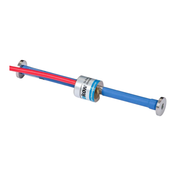
1. INTRODUCTION The Geokon Model 4200ER Vibrating Wire Strain Gage is designed primarily for high range strain measurements in mass concrete, in structures such as foundations, piles, bridges, dams, containment vessels, tunnel liners, etc. See Figure 1. Strains as high as 10,000... -
Page 8: Gage Installation
2. GAGE INSTALLATION The 4200ER strain gages are supplied fully sealed and pre-tensioned with the plucking coil mounted. A preliminary check is advisable and this is made by connecting to the readout box and observing the displayed readout (see readout instructions, Section 3). The observed reading should be around the mid-range position (see Table 1). -
Page 9: Placing The Gage In Concrete
2.2. Placing the Gage in Concrete The Model 4200ER strain gages are normally set into the concrete structure in one of two ways: either by casting the unit(s) into the concrete mix directly or by pre-casting the unit(s) into briquettes that are subsequently cast into the structure. - Page 10 Alternative Method: Tie two short pieces of steel rebar to the existing rebar using nylon Tie-wraps, as shown in Figure 3B. Then tie the strain gage to the short pieces of rebar again using nylon tie wraps. This method avoids the resonance problems associated with the previous method. Figure 3B - Alternative Method for attaching VCE 4200X straingages to rebar.
-
Page 11: Using Pre-Cast Briquettes Or Grouting
2.5. Lightning Protection The 4200ER Embedment Strain Gage, unlike numerous other types of instrumentation available from Geokon, does not have any integral lightning protection components, i.e. transzorbs or plasma surge arrestors. Usually this is not a problem as the gages are installed within concrete or grout and somewhat isolated from potentially damaging electrical transients. - Page 12 Geokon provide locations for installation of these components. Lighting arrestor boards and enclosures are available from Geokon that install at the exit point of the instrument cable from the structure being monitored. The enclosure has a removable top so, in the event the protection board (LAB-3) is damaged, the user may service the components (or replace the board).
-
Page 13: Taking Readings
3. TAKING READINGS The following three sections describe how to take readings using readout equipment available from Geokon. Table 1 shows a 10,000 microstrain range gage, Other ranges are avialbale on request. Model: 4200ER - 10,000 Readout Position: Display Units:... -
Page 14: Operation Of The Gk-405 Readout Box
(Note that the display, although marked μE is not directly in microstrains. The change in digits diplayed must be multiplied by the gage factor given on the calibration sheet to get the true microstrains) The GK-404 will continue to take measurements and display the readings until the OFF button is pushed, or if enabled, when the automatic Power-Off timer shuts the GK-404 off. -
Page 15: Micro-6000 Datalogger
One could calculate these settings by taking an initial reading and then setting the starting frequency to 200 Hz below and the ending frequency 200 Hz above. Model: 4200ER MICRO-6000 Gage 4200 Type: Gage Factor G:... -
Page 16: Data Reduction For The Gk-403, Gk-404 Or Gk-405 In Position D
A typical calibration sheet is shown in Figure 6 It will be noted that the 4200Er output is not very linear varying as much a +/- 3%FS. Therefor it is advisable to use the polynomial expression to aceive greater accuracy. -
Page 17: Temperature Corrections
The effect of temperature on the 4200ER strain gage is complex - it varies depending on the strain level.A Typical temperature correction factor to be applied to the 4200ER-10,000 is as follows: Temperature Correction Factor = +(0.000401*R1 - 1.067)(T1-T0) -
Page 18: Shrinkage Effects
4.3. Shrinkage Effects A well know property of concrete is its propensity to shrink as the water content diminishes, or for the concrete to swell as it absorbs water. This shrinkage and swelling can give rise to large apparent strain changes that are not related to load or stress changes. The magnitude of the strains can be several hundred microstrain. -
Page 19: Troubleshooting
5. TROUBLESHOOTING Maintenance and troubleshooting of embedment strain gages are confined to periodic checks of cable connections and maintenance of terminals. Once installed, the gages are usually inaccessible and remedial action is limited. Consult the following list of problems and possible solutions should difficulties arise. Consult the factory for additional troubleshooting help. -
Page 20: Appendix A - Specifications
APPENDIX A - SPECIFICATIONS A.1 4200ER Strain Gage Model: 4200ER 10,000 Range (nominal): 5.0 ¹ Resolution: Calibration 0.5%FSR Accuracy Sytem Accuracy: 2.0% FSR² Stability: 0.1%FS/yr Linearity: +/-3.0% FSR Thermal variable Coefficient: Frequency Range 400-1200 Dimensions (gage): 6.00 x 0.750"... -
Page 21: Appendix B - Thermistor Temperature Derivation
APPENDIX B - THERMISTOR TEMPERATURE DERIVATION Thermistor Type: YSI 44005, Dale #1C3001-B3, Alpha #13A3001-B3 Resistance to Temperature Equation: 273 2 A B LnR C LnR Equation C-1 Convert Thermistor Resistance to Temperature T Temperature in C. Where: LnR ... -
Page 22: Appendix C - High-Temperature Thermistor Linearization
APPENDIX C - HIGH-TEMPERATURE THERMISTOR LINEARIZATION Resistance to Temperature Equation for US Sensor 103JL1A: T Temperature in C. Where; LnR Natural Log of Thermistor Resistance A 1.127670 10 -3 B 2.344442 10 -4 C ...
Need help?
Do you have a question about the 4200ER and is the answer not in the manual?
Questions and answers