
Related Manuals for Microchip Technology MCP1012


Summary of Contents for Microchip Technology MCP1012
- Page 1 MCP1012 1W Demonstration Board User’s Guide 2020 Microchip Technology Inc. DS50002932A...
- Page 2 Technology, and Symmcom are registered trademarks of Microchip Technology Inc. in other countries. GestIC is a registered trademark of Microchip Technology Germany II GmbH & Co. KG, a subsidiary of Microchip Technology Inc., in other countries. All other trademarks mentioned herein are property of their respective companies.
-
Page 3: Table Of Contents
1.2 MCP1012 Short Overview ................9 1.3 MCP1012 1W Demonstration Board Description ......... 10 1.4 Contents of the MCP1012 1W Demonstration Board Kit ......11 Chapter 2. Installation and Operation 2.1 Getting Started ..................... 13 2.2 Setup Procedure ..................13 Chapter 3. - Page 4 MCP1012 1W Demonstration Board User’s Guide Steps ........................27 6.2 Setup 4B ....................... 28 Introduction......................28 Steps ........................28 Chapter 7. Setup Five 7.1 Setup 5 ......................31 Introduction......................31 Steps ........................31 Appendix A. Schematic and Layouts A.1 Introduction ....................33 A.2 Board –...
-
Page 5: Preface
(neither of the R20, R21, R22, or R23 resistors is con- nected) (setup 1A) as well as a description of the functioning of the MCP1012 in Start-Up mode when it is supplied by the secondary side of the transformer and a load is applied at the output (the resistor R21 - 68is connected through SW1.2) - Page 6 (the resistor R20 - 51is connected through SW1.1). • Chapter 6. “Setup Four” – A description of the functioning of the MCP1012 in Normal Run mode when an external command is applied at PULSE pin and the...
-
Page 7: Conventions Used In This Guide
Curly brackets and pipe Choice of mutually exclusive errorlevel {0|1} character: { | } arguments; an OR selection Ellipses... Replaces repeated text var_name [, var_name...] Represents code supplied by void main (void) user { ... 2020 Microchip Technology Inc. DS50002932A-page 7... -
Page 8: Recommended Reading
MCP1012 1W Demonstration Board User’s Guide RECOMMENDED READING This user's guide describes how to use the MCP1012 1W Demonstration Board. Another useful document is listed below. The following Microchip document is available and recommended as a supplemental reference resource: • MCP1012 Data Sheet - “Primary Side Start-Up IC for Isolated Converters”... -
Page 9: Chapter 1. Product Overview
• Environmentally Friendly, EU RoHS Compliant, Pb-Free 1.2.2 Description The MCP1012 is used as a primary-side start-up IC for starting an off-line Switch Mode Power Converter, exemplified in this user’s guide and the data sheet by a Flyback converter. The primary functions of the MCP1012 are: •... -
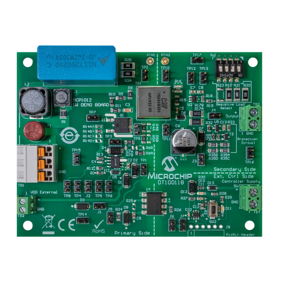
Page 10: Mcp1012 1W Demonstration Board Description
The MCP1012 1W Demonstration Board is used to evaluate and demonstrate Microchip Technology’s MCP1012 product. This board demonstrates the capabilities of the MCP1012 in a Flyback converter application supplied from an external voltage source (120V–500V), with regulated output. FIGURE 1-2: MCP1012 1W Demonstration Board Top View. -
Page 11: Contents Of The Mcp1012 1W Demonstration Board Kit
Product Overview CONTENTS OF THE MCP1012 1W DEMONSTRATION BOARD KIT The MCP1012 1W Demonstration Board kit includes: • MCP1012 1W Demonstration Board (DT100118) • Isolated Jumper JP1 (Mechanical hardware jumper 6.35 mm 1x2 D3087-98) • Important Information Sheet 2020 Microchip Technology Inc. - Page 12 MCP1012 1W Demonstration Board User’s Guide NOTES: 2020 Microchip Technology Inc. DS50002932A-page 12...
-
Page 13: Chapter 2. Installation And Operation
1W DEMONSTRATION BOARD USER’S GUIDE Chapter 2. Installation and Operation GETTING STARTED In order to use and evaluate the capabilities of the MCP1012, several hardware tools are required and several guidelines will be followed. 2.1.1 Required Hardware Tools • MCP1012 1W Demonstration Board (DT100118) •... - Page 14 MCP1012 1W Demonstration Board User’s Guide NOTES: 2020 Microchip Technology Inc. DS50002932A-page 14...
-
Page 15: Chapter 3. Setup One
SETUP 1A INTRODUCTION This setup will show the functioning of the MCP1012 in Start-Up mode when it is supplied by the secondary side of the transformer and no load is applied at the output (neither of the R20, R21, R22, or R23 resistors is connected). -
Page 16: Setup 1B
SETUP 1B INTRODUCTION This setup will show the functioning of the MCP1012 in Start-Up mode when it is supplied by the secondary side of the transformer and a load is applied at the output (the resistor R21 - 68 is connected through SW1.2) STEPS 1. - Page 17 6. Check on the oscilloscope screen the V voltage and the GATE signal as they are presented in Figure 3-2. FIGURE 3-2: MCP1012 V_GATE and V when a Load Is Connected. 7. Disconnect the DC HV power supply. 2020 Microchip Technology Inc. DS50002932A-page 17...
- Page 18 MCP1012 1W Demonstration Board User’s Guide NOTES: 2020 Microchip Technology Inc. DS50002932A-page 18...
-
Page 19: Chapter 4. Setup Two
Chapter 4. Setup Two SETUP 2 INTRODUCTION This setup will show the functioning of the MCP1012 in Start-Up mode when it is supplied by an external power supply (15V) at V pin and a load is applied at the output (the resistor R20 - 51 is connected through SW1.1). - Page 20 MCP1012 1W Demonstration Board User’s Guide 7. Check on the oscilloscope screen the V_GATE voltage and the C/S signal, as they are presented in Figure 4-1. FIGURE 4-1: MCP1012 V_GATE and C/S Voltage. During the Leading Edge Blanking (LEB) period the spikes on C/S pin are ignored. After LEB, once the C/S voltage reaches the threshold of 125 mV, the GATE signal is inhibited.
- Page 21 9. Check on the oscilloscope screen the V_GATE voltage, as it is presented in the Figure 4-3. Set the oscilloscope accordingly. FIGURE 4-3: MCP1012 V_GATE Voltage, t Interval. After V_GATE signal is inhibited, t has a constant interval of 21.0 µs.
- Page 22 MCP1012 1W Demonstration Board User’s Guide NOTES: 2020 Microchip Technology Inc. DS50002932A-page 22...
-
Page 23: Chapter 5. Setup Three
Chapter 5. Setup Three SETUP 3 INTRODUCTION This setup will show the Sleep/Wake-Up functions of the MCP1012 in Start-Up mode when it is supplied by an external power supply (15V) at V pin and a load is applied at the output (the resistor R20 - 51 is connected through SW1.1). - Page 24 MCP1012 1W Demonstration Board User’s Guide 8. Push the push button SW2 and check on the oscilloscope screen the V_GATE voltage and the PULSE signal, as they are presented in Figure 5-1 Figure 5-2. FIGURE 5-1: MCP1012 Sleep Command. Five pulses applied on PULSE pin negative edge at 500 kHz activate the Sleep function of the MCP1012.
- Page 25 (return to Start-Up mode). 11. Read the voltmeter and check if the output voltage of the board is in the range of 4.5V to 5.5V. 12. Disconnect the DC power supplies. 2020 Microchip Technology Inc. DS50002932A-page 25...
- Page 26 MCP1012 1W Demonstration Board User’s Guide NOTES: 2020 Microchip Technology Inc. DS50002932A-page 26...
-
Page 27: Chapter 6. Setup Four
Chapter 6. Setup Four SETUP 4A INTRODUCTION This setup will show the functioning of the MCP1012 in Normal Run mode when an external command is applied at PULSE pin and the C/S pin voltage does not reach the COMP1 Reference (252 mV). -
Page 28: Setup 4B
V_PULSE, V_GATE and V_CS when COMP1 Reference Is Not Reached. When a valid PWM signal in the 20–65 kHz frequency range is applied the MCP1012’s gate driver is driven by the signal at the PULSE pin and not by the internal signal. The COMP1 Reference threshold during external command switches from 125 mV to 252 mV typical. - Page 29 When the voltage on the C/S pin reaches the COMP1 reference (typ. 252 mV), the Gate command is turned off even if the PULSE logic state is Low. 9. Disconnect the DC power supplies. 2020 Microchip Technology Inc. DS50002932A-page 29...
- Page 30 MCP1012 1W Demonstration Board User’s Guide NOTES: 2020 Microchip Technology Inc. DS50002932A-page 30...
-
Page 31: Chapter 7. Setup Five
Chapter 7. Setup Five SETUP 5 INTRODUCTION This setup will show the functioning of the MCP1012 in Start-Up mode when a short circuit is created on the secondary side of the transformer. STEPS 1. Connect/disconnect the jumpers and the switch SW1 according to Table 7-1. - Page 32 MCP1012 V_GATE Voltage during a Short Circuit Condition. 8. Disconnect the DC power supplies. 9. Disconnect the jumper J4. 10. Reconnect the DC power supplies. Check the functionality of the MCP1012 by running the setups described in this user’s guide. 2020 Microchip Technology Inc. DS50002932A-page 32...
-
Page 33: Appendix A. Schematic And Layouts
MCP1012 1W DEMONSTRATION BOARD USER’S GUIDE Appendix A. Schematic and Layouts INTRODUCTION This appendix contains the following schematic and layouts for the MCP1012 1W Demonstration Board: • Board – Schematic • Board – Top Silk • Board – Top Copper and Silk •... -
Page 34: Board - Schematic
0805 GNDS BC807 0805 4.7k 1000pF 0805 SMAJ22A 1000pF R35A R35C 330R 330R P6KE510 1206 1206 0805 TLV431A-D VDD_EXT MCP1012 R35B R35D 1.3k 330R 330R PIC_VDD IPD90R1K2C3ATMA1 0805 1206 1206 US1M GATE US1M 0805 GNDS GNDS GNDS PULSE TERMINAL 1x2... -
Page 35: Board - Top Silk
Schematic and Layouts BOARD – TOP SILK BOARD – TOP COPPER AND SILK 2020 Microchip Technology Inc. DS50002932A-page 35... -
Page 36: Board - Top Copper
MCP1012 1W Demonstration Board User’s Guide BOARD – TOP COPPER BOARD – BOTTOM COPPER 2020 Microchip Technology Inc. DS50002932A-page 36... -
Page 37: Board - Bottom Copper And Silk
Schematic and Layouts BOARD – BOTTOM COPPER AND SILK BOARD – BOTTOM SILK 2020 Microchip Technology Inc. DS50002932A-page 37... - Page 38 MCP1012 1W Demonstration Board User’s Guide NOTES: 2020 Microchip Technology Inc. DS50002932A-page 38...
-
Page 39: Appendix B. Bill Of Materials (Bom)
SMAJ22A 400W SMD DO-214AC_SMA Diode, TVS, P6KE510 434V Micro Commercial SMBJP6KE510A-TP 600W DO-214AA_SMB Components Corp. (MCC) Diode, Schottky, BAT46W-TP Micro Commercial BAT46W-TP 450 mV 10 mA 100V, surface Components Corp. (MCC) mount, SOD-123 2019 Microchip Technology Inc. DS50002932A-page 39... - Page 40 MCP1012 1W Demonstration Board User’s Guide TABLE B-1: BILL OF MATERIALS (BOM) (CONTINUED) Qty. Reference Description Manufacturer Part Number ® Diode, Schottky, DFLS1200-7 Diodes Incorporated DFLS1200-7 850 mV 1A 200V POW- ERDI-123 Diode, zener, SMAZ18-13-F Diodes Incorporated SMAZ18-13-F 18V 1W DO-214AC_SMA Diode, LED, red 2.2V 20 mA...
- Page 41 Resistor, TKF 4.7k 5% 1/8W Panasonic ERJ-6GEYJ472V surface mount, 0805 Resistor, TKF 5.6k 1% 1/8W, Vishay Dale CRCW08055K60FKEA surface mount, 0805 Switch, DIP 4 SPST 24V TE Connectivity 1-1825059-3 100 mA 1-1825059-3, surface mount 2019 Microchip Technology Inc. DS50002932A-page 41...
- Page 42 MCP1012 1W Demonstration Board User’s Guide TABLE B-1: BILL OF MATERIALS (BOM) (CONTINUED) Qty. Reference Description Manufacturer Part Number ® Switch, tact. SPST 12V 50mA E-Switch , Inc. TL3302AF180QJ TL3302AF180QJ, surface mount ® Transistor, BJT, PNP ON Semiconductor BC807-16LT1G BC807-16L -45V -500 mA 225 mW SOT-23-3 Connector, terminal 5.08 mm...
-
Page 43: Worldwide Sales And Service
New York, NY Tel: 46-31-704-60-40 Tel: 631-435-6000 Sweden - Stockholm San Jose, CA Tel: 46-8-5090-4654 Tel: 408-735-9110 UK - Wokingham Tel: 408-436-4270 Tel: 44-118-921-5800 Canada - Toronto Fax: 44-118-921-5820 Tel: 905-695-1980 Fax: 905-695-2078 2020 Microchip Technology Inc. DS50002932A-page 43 05/14/19... - Page 44 Mouser Electronics Authorized Distributor Click to View Pricing, Inventory, Delivery & Lifecycle Information: Microchip DT100118...
Need help?
Do you have a question about the MCP1012 and is the answer not in the manual?
Questions and answers