Table of Contents
Advertisement
Quick Links
Instructions
LubeMaster
Mount or Wall Mount
Pump Package
Provides a constant supply of lubrication to pump components. For professional use only.
Maximum Working Pressure: 5000 psi (340 bar, 34.0 MPa)
The LubeMaster Pump Package includes the following
components:
•
Reservoir
•
Oil or Grease Pump
See page 6 for part number information.
Important Safety Instructions
Read all warnings and instructions in this manual. Save
these instructions.
®
Floor
3A2781A
EN
Advertisement
Table of Contents

Related Manuals for Graco LubeMaster


Summary of Contents for Graco LubeMaster
- Page 1 Mount or Wall Mount 3A2781A Pump Package Provides a constant supply of lubrication to pump components. For professional use only. Maximum Working Pressure: 5000 psi (340 bar, 34.0 MPa) The LubeMaster Pump Package includes the following components: • Reservoir •...
-
Page 2: Table Of Contents
Clutch Drive Assembly ....29 LubeMaster Pump ..... . . 30 Motors and Drives . -
Page 3: Part Number
The Codes associated with each Option (A-D) that make up the Part Number are provided in the tables below. For example, Part Number - LM1321 is a LubeMaster pump system with a 12 pint plastic oil reservoir. It has a 10:1 reduction ratio and is floor mounted. -
Page 4: Warnings
Warnings Warnings The following warnings are for the setup, use, grounding, maintenance, and repair of this equipment. The exclama- tion point symbol alerts you to a general warning and the hazard symbols refer to procedure-specific risks. When these symbols appear in the body of this manual or on warning labels, refer back to these Warnings. Product-specific hazard symbols and warnings not covered in this section may appear throughout the body of this manual where applicable. - Page 5 Warnings EQUIPMENT MISUSE HAZARD Misuse can cause death or serious injury. • Do not operate the unit when fatigued or under the influence of drugs or alcohol. • Do not exceed the maximum working pressure or temperature rating of the lowest rated system com- ponent.
-
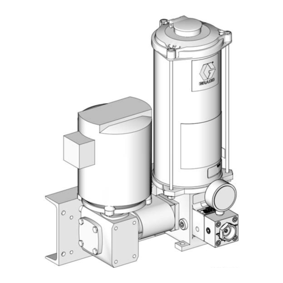
Page 6: System Identification
System Identification System Identification (Floor Mount Model Shown) Grease Model Oil Model Side View Pump Adjustment Nut Pump Inlet Drive Shaft Pressure Gauge Drain and Drain Plug (Oil Models: one on each side of base); (Grease Models: one on the opposite side of the base from the fill stud (13) Pump Outlet 11 Reservoir Assembly (Oil or Grease) -
Page 7: Component Identification
Component Identification Pump (101) • The pump can be driven by an electric motor or by a All LubeMaster Pump Packages include the following rotating or oscillating machine motion. components: • The pump must always be installed with the reser- •... -
Page 8: Installation Instructions
F . 1. Location Components are completely assembled when you first receive the LubeMaster Pump Package from the factory. Reassembly instructions for these components are pro- vided in the Maintenance and Repair section of this manual, beginning on page 17. -
Page 9: Setup
Setup Setup Filling the Reservoir Filling Oil Reservoirs Oil reservoirs have a fill cap (30) and filter (31). Material Cleanliness Make sure that lubricant used to fill the system is clean. If there is doubt about cleanliness, lubricant should be filtered before being introduced into the system. - Page 10 Setup Filling Grease Reservoirs 1. Remove cover (12) 2. Connect grease supply source to fill stud (13). 3. Loosen the drain plug (E) (located on the opposite side of the base from the fill stud (13) (F . 6). OVER PRESSURIZATION HAZARD Over pressurization can result in equipment rupture and serious injury.
-
Page 11: System Filling
Setup System Filling NOTE: Manual air bleeding procedures are necessary in the event any system components are loosened, dis- connected or otherwise removed after their initial instal- After the reservoir is filled as described in Filling the lation. Reservoir, page 9, fill the remainder of the system by attaching a hand pump to the system downstream from the pump manifold block assembly and cycle the hand Adjusting the Clutch Drive... -
Page 12: Standard Pump Adjustment
Setup Clutch Drive - Calculating Pump Output The standard pump output can be varied, from 0.010 to 0.050 cubic inches (0.1639 to 0.8195 cu. cm) per cycle, by changing the position of the pump adjustment sleeve (2) (F . 1, page 6) located below the pressure gauge (3). The high volume pump has a fixed output. -
Page 13: Operation
Operation Operation While the system is operating, periodically check the following components: • Check that the pump is cycling according to sched- ule. • Visually check the unit for leaks and loose fittings. Make sure that hoses do not become kinked and are not rubbing on anything. -
Page 14: Troubleshooting
If unit is still not functioning, repair or defective replace timer/controller. Key is sheared or missing at coupling Replace key. Gearbox must be replaced. For this No Gear Reducer Output Defective gearbox repair unit must be returned to an authorized Graco repair facility. 3A2781A... - Page 15 If there is output, replace clutch. For this repair unit must be Clutch drive is operating but there is Clutch is defective returned to an authorized Graco no flow repair facility. • If there is no output, see Pump is...
- Page 16 Troubleshooting Problem Cause Solution Tighten hex nuts (1). Torque to 5 ft. Hex nuts (1) are not tight lbs (6.78 N•m) Damaged or worn gasket (8) Replace gasket (8) Lubricant is leaking from the reser- Cracks or nicks in reservoir tube (11) Replace reservoir tube (11) voir or reservoir is dented or out-of-round...
-
Page 17: Maintenance And Repair
Maintenance and Repair Maintenance and Repair Pumps: Oil and Grease Models 1. Disconnect all electrical power and air supplies to the pump. 2. Relieve pressure, page 13. 3. For pumps with oil reservoirs, remove pipe plug (116, F . 10) and drain oil into a suitable, clean AUTOMATIC SYSTEM ACTIVATION HAZARD container. -
Page 18: Grease Reservoirs
Maintenance and Repair Grease Reservoirs Disassembly The disassembly procedure may be performed with the reservoir mounted on the pump. However, some mount- ing locations are too restrictive to provide access to all components. If installation requires dismounting of the reservoir, drain the reservoir of lubricant before removing the attaching hardware. -
Page 19: Low-Level Switch Assemblies
Maintenance and Repair Assembly 2. Disconnect and remove all wiring from the low level switch (304). Before assembling, lubricate followers and tube inner diameter with the same lubricant used in the system. 3. Remove low level switch (304) from bracket (a). 4. -
Page 20: Oil Reservoirs
Maintenance and Repair Oil Reservoirs Disassembly The disassembly procedure may be performed with the reservoir mounted on the pump. However, some mount- ing locations may be too restrictive to provide access to all components. If installation requires dismounting of the reservoir, Refer to F . - Page 21 Maintenance and Repair 15 Amp Low-Level Switch Assembly Option 6. Unscrew low-level lower assembly (304e) from low-level adapter (304b). 7. Unscrew low-level adapter (304b) from reservoir cover. 8. Remove low-level adapter (304b) from union nut (304c). Refer to F . 15 for reference numbers used in the fol- lowing instructions.
- Page 22 Maintenance and Repair 10-Watt Low-Level Assembly Options Assembly The following procedure is used for installing a new assembly in a reservoir. If your assembly was removed for repairs, steps 1 and 2 do not apply. 1. Remove the cover (9) from the reservoir (11). Refer to F .
- Page 23 Maintenance and Repair Overhead Supply Adapter Refer to F . 18 for reference numbers used in the fol- lowing instructions. Disassembly The disassembly procedure may be performed with the adapter mounted on the pump. However, some mount- ing locations may be too restrictive to provide access to all components.
-
Page 24: Installation After Maintenance
1,500 hours and, thereafter, at The clutch drive assembly replacement part number 5,000 hour intervals. 563383 is available from Graco. Contact your local Graco distributor for assistance in ordering this part. Alternative AGMA Lubricants MANUFACTURER LUBRICANT NAME AGMA RATING Getty Refining Co. -
Page 25: Parts
Parts Parts Grease Reservoirs: 562896, Ref Part No. Description Qty. NUT, 5/16-18 hex 562897, 562898, 562899 NUT, elastic lock 5/16-18 hex (not shown) ROD, tie, reservoir RING, retainer, 1/2 ID WASHER, lock WASHER, reservoir (models 562896, 562897 only) 8 GASKET, reservoir COVER, reservoir SPRING, follower 11... -
Page 26: Oil Reservoirs
Parts Parts Oil Reservoirs: 562892, 562893, Ref. Part No. Description Qty. 562894, 562895 NUT, 5/16-18 hex ROD, tie, reservoir WASHER, lock PLUG, dryseal 1/4 nptf 8 GASKET, reservoir COVER, reservoir 11 RESERVOIR 30 557797 CAP, fill, reservoir 31 557799 SCREEN, filter 32 563380 PUMP, assembly ... -
Page 27: Overhead Supply Adapter Assembly
Parts Overhead Supply Adapter Assembly 562908 Part No. Description Qty. NUT, 5/16 - 18 hex PLUG, stl 1/2 pipe hex soc (not shown) SCREW, hex hd cap, 5/16 WASHER, lock 557333 GASKET, 6, 12, 20 lb reservoir 557334 GASKET, lower reservoir PLUG, dryseal 1/4 nptf CAP, resv 12 lb bolt TUBE, adapter... -
Page 28: Pump Body Assembly
Parts Pump Body Assembly: 563380 . 19 Parts Description Qty. 557644 BODY, pump BEARING, ball, 0.50 ID x 1.37 OD 556361 (not shown) PLATE, end SHAFT, assembly 560773 YOKE SPACER, 0.75 ID x 0.344 long SPACER, 0.75 ID x 0.969 long SCREW, SHCS 5/16 -18 x 0.50 SCREW, SOC head cap, 5/16 WASHER... -
Page 29: Clutch Drive Assembly
Parts Clutch Drive Assembly: 563383 3A2781A... -
Page 30: Lubemaster Pump
Parts LubeMaster Pump Ref. Part No. Description Ref. Part No. Description 307c SCREW, cap hex hd (models 557271 MOTOR, 115/230 volt, sin- 563386, 563387) gle-phase, 1/2 hp,1725 rpm SCREW, cap, hex hd (models 557270 MOTOR, 230/460 volt, 563388, 563389) three-phase, 1/2 hp, 1725 rpm... -
Page 31: Floor Mounting
Parts Motorized LubeMaster Pump with Gear Reducer and Motor (Up to 20 lbs): Floor Mounting 563388 - Base, Floor Mounting 10:1 563389 - Base, Floor Mounting 60:1 307b/307m 307d 307d 307a 307a 307w 307g/ 307t 307r 307h 3A2781A... -
Page 32: Wall Mounting
Parts Motorized LubeMaster Pump with Gear Reducer and Motor (Up to 20 lbs): Wall Mounting 563386 - Base, Wall Mounting 10:1 563387 - Base, Wall Mounting 60:1 307c/ 307y 307a/ 307z 307r 307m 307g/ 307v 307h 307t 3A2781A... -
Page 33: Oil Reservoir 15 Amp Low-Level Assemblies
Parts Oil Reservoir 15 Amp Low-Level Oil Reservoir 10-Watt Low-Level Assemblies Assemblies 304k 304d 304a 304c 304b 304e 304m 304n 304h 304p 304g 304f ti27678 Part No. Description Qty. Part No. Description Qty. 563015 SWITCH, low level 12 pint 563016 SWITCH, low level 20 pint 563316 SWITCH, low level assy 5 &... -
Page 34: Grease Reservoir Low-Level Assembly
Parts Grease Reservoir Low-Level Assembly 304u 304t 304s 304v 304r Part No. Description Qty. 563322 SWITCH, low level grease reservoir 304r SCREW, 1/4-20 x 3/8 hex hd washer 304s RETAINER, cup spr 304t BRACKET, sw low lever paint 304u SWITCH, limit spdt 304v SPRING, primer filter 3A2781A... -
Page 35: Technical Data
Technical Data Technical Data LubeMaster® Floor Mount or Wall Mount Pump Package Metric Pump Data Maximum fluid working pressure 5,000 psi 34 MPa, 340 bar Max Torque @ Rated Max Pressure 27 ft-lbs 36.61 N.m Output Range 0.010 - 8.75 in. - Page 36 Technical Data LubeMaster® Floor Mount or Wall Mount Pump Package Metric 115/230V 1/2 hp single phase 60 Hz 1725 RPM, T.E. Full load run- ning current 115 Volts, 7.4 Amps; 230 Volts, 3.7 Amps. Inrush at 115 Volts 49 AMPS; 230 Volts 24.5 AMPS.
-
Page 37: Dimensions
Dimensions Dimensions Reservoirs A- Dimension Reservoir Size Inches 12 Pint Oil 19.56 496.9 12 Lb. Grease 20 Pint Oil 26.56 674.7 20 Lb. Grease Overhead Supply 7.66 194.5 3A2781A... -
Page 38: Reservoirs
Dimensions Reservoirs A- Dimension Reservoir Size Inches 12 Pint Oil 19.56 496.9 12 Lb. Grease 20 Pint Oil 26.56 674.7 20 Lb. Grease 3A2781A... -
Page 39: Clutch Drive
Dimensions Clutch Drive A- Dimension Reservoir Size Inches 12 Pint Oil 19.56 496.9 12 Lb. Grease 20 Pint Oil 26.56 674.7 20 Lb. Grease 3A2781A... -
Page 40: Clutch Drive
Dimensions Clutch Drive 3A2781A... -
Page 41: Motorized Lubemaster (Up To 20Lbs): Wall Mounting
Dimensions Motorized LubeMaster (Up to 20lbs): Wall Mounting Inches (mm) 3A2781A... -
Page 42: Motorized Lubemaster (Up To 20Lbs): Floor Mounting
Dimensions Motorized LubeMaster (Up to 20lbs): Floor Mounting Inches (mm) 3A2781A... -
Page 43: Motorized Lubemaster (Up To 20Lbs)
Dimensions Motorized LubeMaster (Up to 20lbs) Inches (mm) 2.03 11.03 (51.59) (280.19) 3A2781A... -
Page 44: Graco Standard Warranty
With the exception of any special, extended, or limited warranty published by Graco, Graco will, for a period of twelve months from the date of sale, repair or replace any part of the equipment determined by Graco to be defective.
Need help?
Do you have a question about the LubeMaster and is the answer not in the manual?
Questions and answers