Table of Contents
Advertisement
Quick Links
Download this manual
See also:
Operating Manual
Advertisement
Table of Contents

Related Manuals for wtw IFL 700 IQ


Summary of Contents for wtw IFL 700 IQ
- Page 1 OPERATING MANUAL ba75990e02 08/2014 IFL 700 IQ IFL 700 IQ IFL 701 IQ IQ S SLUDGE LEVEL SENSOR ENSOR...
- Page 2 IFL 70x IQ © Copyright 2012 Xylem Analytics Germany GmbH Printed in Germany. ba75990e02 08/2014...
-
Page 3: Table Of Contents
IFL 70x IQ Contents IFL 70x IQ - Contents Overview ........1-5 How to use this component operating manual . - Page 4 Contents IFL 70x IQ What to do if....... . . 6-27 Technical data ......7-30 Measurement characteristics .
-
Page 5: Overview
IFL 70x IQ Overview Overview How to use this component operating manual Structure of the IQ S IQ Sensor Net Operating Manual ENSOR operating manual System Operating Manual (Ring Binder) IQ Sensor MIQ Module MIQ Terminal Operating Operating Operating Manual Manual Manual Component Operating Manuals... -
Page 6: Structure Of The Ifl 70X Iq Sludge Level Sensor
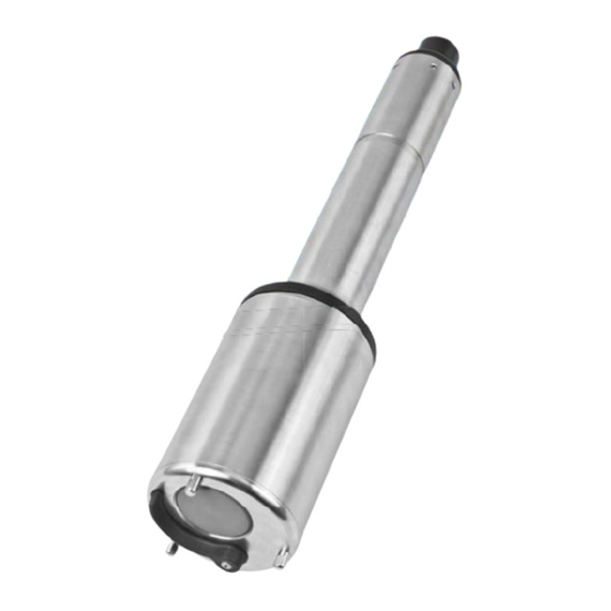
Overview IFL 70x IQ Structure of the IFL 70x IQ sludge level sensor Structure Fig. 1-2 Structure of the sludge level sensor (example: IFL 700 IQ) Wiper (only IFL 700 IQ) Ultrasonic transducer Marking for immersion depth 0.1 m Shaft... -
Page 7: Recommended Fields Of Application
Echo reflected by the sludge blanket (short reflection interval) Echo reflected by the bottom area (long reflection interval) Wiper (cleaning The IFL 700 IQ sensor has a mechanical wiper that effectively cleans gas system) bubbles and dirt off the ultrasonic transducer. The wiper operates contactless and is maintenance-free and wear-free. -
Page 8: Safety Instructions
Safety instructions IFL 70x IQ Safety instructions Safety information 2.1.1 Safety information in the operating manual This operating manual provides important information on the safe operation of the product. Read this operating manual thoroughly and make yourself familiar with the product before putting it into operation or working with it. The operating manual must be kept in the vicinity of the sensor so you can always find the infor- mation you need. -
Page 9: Safe Operation
IFL 70x IQ Safety instructions Safe operation 2.2.1 Authorized use The authorized use of the IFL 70x IQ consists of its use as a sensor in the IQ S . Only the operation and running of the sensor according to the ENSOR instructions and technical specifications given in this operating manual is autho- rized (see chapter 8 T... -
Page 10: Commissioning
Controller software: Version 3.35 or higher MIQ/TC 2020 XT Terminal software: Version 3.35 or higher Scope of delivery Sludge level sensor IFL 700 IQ or IFL 701 IQ Operating manual Installation 3.3.1 General information NOTE Sharp objects can damage the ultrasonic transducer. Please be careful, es- pecially when handling sharp tools, when cleaning and during transport. -
Page 11: General Installation Conditions
IFL 70x IQ Commissioning 3.3.2 General installation conditions Minimum distance = 0.2 m + 0.05 * (water depth - immersion depth in m) from basin wall Immersion depth Wall (= 0.1 m) Immersion depth Dead zone (= 0.4 m) Vertical installation Depth of the sludge level... -
Page 12: Influence Of Permanently Installed Fixtures
If there are range problems, the sensor must be immersed deeper (note the dead zone and maximum depth of immersion). With the IFL 700 IQ sensor, the mechanical wiper removes gas bubbles and dirt from the surface of the ultrasonic transducer. -
Page 13: Short-Term Interferences Due To Obstacles
SACIQ standard model, the SACIQ SW sensor connection cable is opti- mized concerning its resistance to corrosion. Information on this and other IQ S accessories is given in the WTW catalog and on the Internet. ENSOR How to connect the SACIQ (SW) sensor connection cable to the... - Page 14 Then screw the coupling ring (2) of the sensor connection cable onto the sensor up to the stop. NOTE (only IFL 700 IQ) If the sensor is connected to the IQ S , the mechanical wiper may ENSOR start moving unexpectedly.
-
Page 15: Initial Commissioning
ENSOR ware version of the controller and the terminal. The current software is available on the Internet under www.WTW.com. Install the sensor at the measuring location and establish the connec- tion to the IQ S . (see section 3.3). - Page 16 Commissioning IFL 70x IQ Fig. 3-3 Sample echo profile (sludge blanket height) Entered Water depth (shaded) Move the cursor along the profile (with < >) Topmost echo: First rise of the sludge concentration viewed from the surface of the water Strongest echo: Most concentrated sludge (greatest intensity) Status line (values at the cursor position)
-
Page 17: Setting Table For The Ifl 70X Iq
IFL 70x IQ Commissioning Fig. 3-4 Measured value display with main and secondary measured value Measured value Number of echoes found Setting table for the IFL 70x IQ Default values are marked in bold. 3.5.1 Sensor settings menu Carrying out The sensor settings can be accessed from the following menus: settings ... - Page 18 Commissioning IFL 70x IQ Setting Selection/values Explanation Sludge level depth Position of the sludge blanket level in rela- tion to the surface of the water (SLD). Unit Selection of the unit for the distance Meter Foot Immersion depth 0.05 ... 0.10 ... 3.00 m Distance between the surface of the ultra- sonic transducer (underside of the sen- sor) and the surface of the water (see Fig.
- Page 19 IFL 70x IQ Commissioning Setting Selection/values Explanation The rising side of the echo is evaluated for Method the measured value determination. One of two methods can be selected for this. Rel. threshold The measured value is equivalent to the point where the intensity of the echo reaches the adjusted relative threshold.
- Page 20 Commissioning IFL 70x IQ Setting Selection/values Explanation With this setting, the echo to be evaluated Echo selection is determined. The echo is automatically identified according to the criterion that was set. Topmost echo The topmost echo (from the surface of the water) is used for calculating the mea- sured value.
- Page 21 IFL 70x IQ Commissioning Setting Selection/values Explanation Establishing time 0 ... 120 ... 600 sec Filter that ignores (interfering) echoes whose residence time within the ultra- sonic cone is shorter than the time defined here. Example: To ignore a scraper, the maxi- mum duration of its visibility in the ultra- sonic cone has to be entered.
-
Page 22: Display/Extras Menu
Unfiltered Displays the echo profile without any fil- ters. Filtered Displays the echo profile with all filters. Apply Closes the Display/Extras menu. Scraper test (only with IFL 700 IQ ) The wiper moves once (function test). ba75990e02 08/2014... -
Page 23: Measuring
IFL 70x IQ Measuring Measuring Submerse the sensor in the sample. Read the measured value on the terminal of the IQ S ENSOR system. Factors affecting the The following factors have an impact on the measured value: measured value The environmental conditions at the measuring location deviate too much from the sensor settings (Immersion depth, Water depth, Temperature) ... -
Page 24: Maintenance, Cleaning, Accessories
Sharp objects can damage the ultrasonic transducer. Please be careful, espe- cially when handling sharp tools, when cleaning and during transport. NOTE (only IFL 700 IQ) If the sensor is connected to the IQ S , the mechanical wiper may start ENSOR moving unexpectedly. - Page 25 NOTE Carefully clean the wiper of the IFL 700 IQ from outside. Clean the sensor shaft and the surface of the ultrasonic transducer as explained in the point C , page 24.
-
Page 26: Accessories
Maintenance, cleaning, accessories IFL 70x IQ Accessories Information on IQ S accessories is given in the WTW cat- ENSOR alog and on the Internet. ba75990e02 08/2014... -
Page 27: What To Do If
IFL 70x IQ What to do if... What to do if... Mechanical Cause Remedy damage to the – Return the sensor sensor Display "----" Cause Remedy (no valid measured Sensor is permanently in the air Immerse the sensor in water (see value) section 3.3.2) There are too many air bubbles in... - Page 28 What to do if... IFL 70x IQ The measured Cause Remedy value is not within The Water depth is not set correctly Set the Water depth and Immersion the expected range depth correctly (e.g., the bottom echo or multiple echoes between the bottom of the basin and the surface of the water are interpreted as measured value echoes.)
- Page 29 IFL 70x IQ What to do if... Number and Cause Remedy position of the Small temporary interfering – Check Echo selection (Topmost echoes changing echoes echo or Strongest echo) often – A higher value for the Minimum (e.g. sludge flakes sinking slowly) intensity filter ignores echoes from small, slowly sinking sludge fields.
-
Page 30: Technical Data
Technical data IFL 70x IQ Technical data Measurement characteristics Measuring Ultrasound echo measurement principle Measuring ranges Measured Measuring ranges Resolution Accuracy and resolution parameter Distance 0.4 ... 15 m from 0.01 m 0.1 m ultrasonic trans- ducer surface Conversion to sludge level depth (from the surface of the water) or sludge level height (from the bottom of the basin) Application characteristics Allowed... -
Page 31: General Data
Material Shaft and enclosure V4A stainless steel 1.4571 Base plate V4A stainless steel 1.4571 Ultrasonic transducer surface PVC-C Wiper (only IFL 700 IQ) Grivory Wiper driving shaft Titan (grade 2) (only IFL 700 IQ) Plug head connector housing ® Plug, 3-pole... -
Page 32: Electrical Data
ECHNICAL DATA IQ S system operating ENSOR manual) Power consumption IFL 700 IQ 5.5 W (maximum power consumption) 3.0 W (average power consumption) If the sensor is supplied with power by an MIQ/WL PS or DIQ/ S 28X module, only the average power consumption has to be taken into account. -
Page 33: Indexes
The last three digits of the message code form the component code. It identifies the component (active component) that caused the message: Some error messages contain an internal error code, starting with "#". Module code Component IFL 700 IQ IFL 701 IQ 8.1.1 Error messages Message code Message text EI13Cx... -
Page 34: Info Messages
Indexes IFL 70x IQ Message code Message text ESD3Cx No echo profile * Clean and immerse the sensor * Check the sensor fixations and fix the sensor in a vertical measuring position 8.1.2 Info messages The sensor does not generate any info messages. Status info The status info is a coded piece of information on the current status of a sensor. - Page 36 For more information on how Xylem can help you, go to xyleminc.com. ® Service address: Xylem Analytics Germany Sales GmbH & Co. KG Dr.-Karl-Slevogt-Str. 1 82362 Weilheim Germany Tel.: +49 881 183-325 Fax: +49 881 183-414 E-Mail wtw.rma@xyleminc.com Internet: www.WTW.com Xylem Analytics Germany GmbH Dr.-Karl-Slevogt-Str. 1 82362 Weilheim Germany...
Need help?
Do you have a question about the IFL 700 IQ and is the answer not in the manual?
Questions and answers